
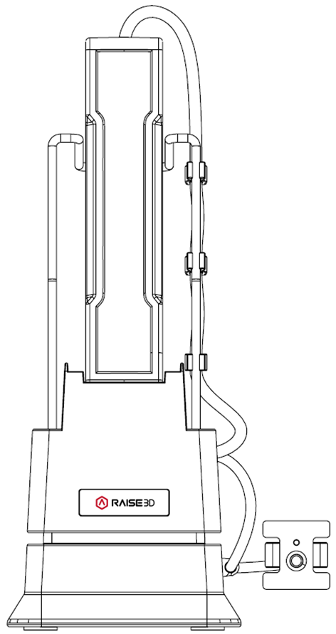
A.1 Introduction to the DF2 Auto-Feeding Station
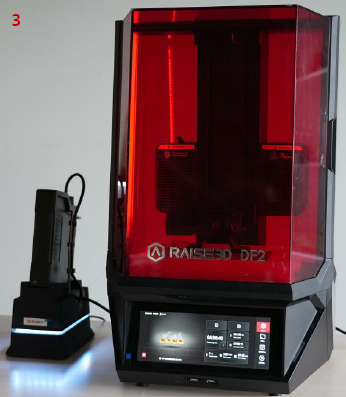
The Raise3D DF2 Auto-Feeding Station is an accessory for the Raise3D DF2. The DF2 and the auto-feeding station work together to ensure there is always enough resin available to complete the current print task.
A.2 Technical Specification
Item | Raise3D DF2 Auto-Feeding Station |
Size (W × D × H) | 222 mm x 140 mm x 355 mm (8.7 in x 5.5 in x 14 in) |
Weight (without liquid resin) | 2.4 kg |
Operating Ambient Temperature | 15-30°C, 10-90% RH, non-condensing |
Storage Temperature | -25 °C to +55 °C, 10-90% RH, non-condensing |
Power Supply Input | 12 V DC |
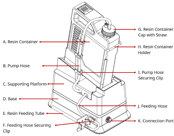
A.3 Main Parts
A.4 Accessories List
Item | Name | Purpose | Quantity | Unit |
1 | 1 Liter Resin Container Holder | To hold the resin container with a 1-liter capacity | 1 | Piece |
2 | 3 Liter Resin Container Holder | To hold the resin container with a 3-liter capacity | 1 | Piece |
3 | Resin Container Cap with Straw | To seal and pump the resin | 2 | Piece |
4 | Pump | To pump liquid resin | 1 | Piece |
5 | Hoses: Pump Hose (short), Feeding Hose (long) | To transport liquid resin | 4 | Piece |
6 | Resin Feeding Tube | Guides the liquid resin into the resin tank of the DF2 | 2 | Piece |
7 | Connection Cable | Connects the DF2 auto-feeding station to the DF2 to transmit power and signal | 1 | Piece |
8 | Pump Hose Securing Clip | To secure the pump hose | 6 | Piece |
9 | Resin Feeding Tube Sealing Cap | Blocks the outlet of the resin feeding tube to avoid resin overflow | 2 | Piece |
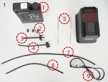
B.1 Assemble the DF2 Auto-Feeding Station
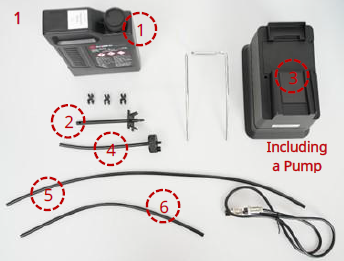
Prepare the following items before assembly, as shown in image 1:
1. Resin container with an appropriate amount of liquid resin x1
2. Pump hose securing clips x3
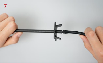
3. Resin feeding tube x1
4. Resin container cap with straw x1
5. Resin container holder (1L/ 3L) x1
6. Main body: supporting platform + base (with a pump installed) x1
7. Feeding hose (long) x1
8. Pump hose (short) x1
9. Connection cable x1
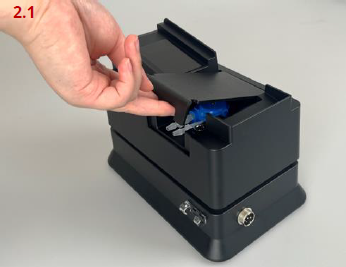
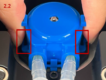
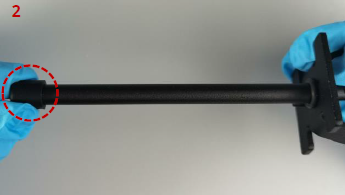
Remove the pump cover from the supporting platform. Pinch the pump buckles inwards (as shown in the red boxes in image 2.2) and remove the pump from the slot.
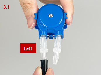
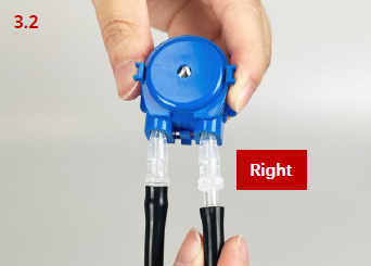
As shown in the images on the left, the pump hose (short) should be connected to the left hose barb on the pump, and the feeding hose (long) should be connected to the right hose barb on the pump.
Note: When installing the hoses onto the pump barbs, ensure that each hose is fully seated onto each barb.
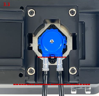
Place the pump into the slot. Keep the outlet of the pump parallel to the side of the supporting platform (as shown by the red dashed line in image 3.3).
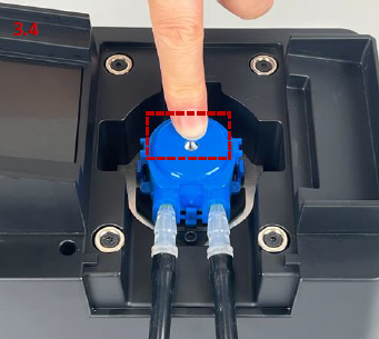
Place your finger in the position shown in the red box in image 3.4. To install the pump in place, gently apply pressure downward until a "click" is heard. Then re-install the pump cover.
Note: Please press the pump at the point illustrated shown in the red box in image 3.4, otherwise the pump cannot be pressed into position. If pressed with too much force or at the wrong point, the pump buckles may be damaged.
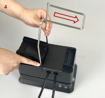
Insert the resin container holder into the holes on the supporting platform. Ensure that the orientation of the container holder is correct as shown in image 4.
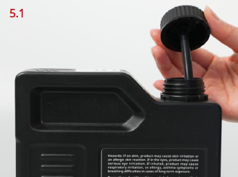
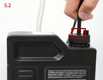
Replace the original resin container cap with the resin container cap with straw. As shown in the red box in image 5.2, connect the pump hose (short) to the barb on top of the resin container cap with straw. Once the connection is made, slide the resin container into the holder and place it onto the supporting platform.
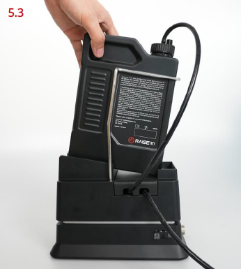
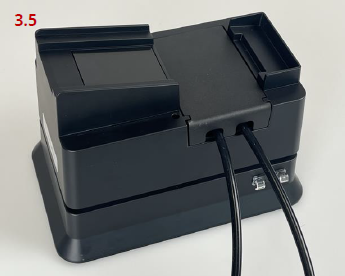
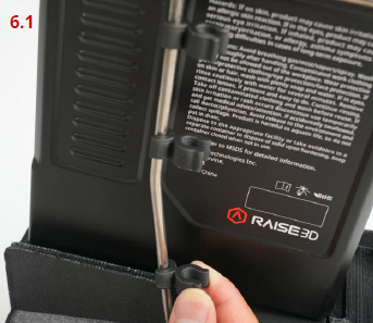
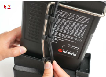
As shown in the images on the left, install the pump hose securing clips onto the container holder and space them evenly. When the clips are in place, gently route the pump hose (short) and secure it with the other end of the clips. Then secure the feeding hose (long) into the feeding hose securing clip on the base.
Insert the other end of the feeding hose (long) into the barb on the resin feeding tube.
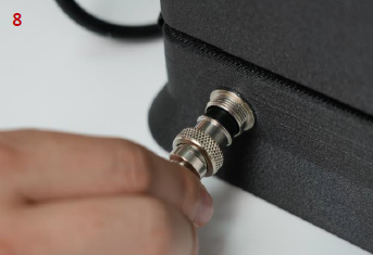
Install the connection cable to the connection port on the base and tighten it.
Note: The notches on the connector need to be aligned.
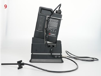
Assembly of the DF2 auto-feeding station has been completed.
B.2 Fill the Liquid Resin
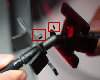
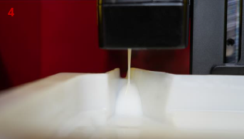
Insert the resin feeding tube into the hole for the resin feeding tube on the back of the DF2 and align it with the pouring spout of the resin tank.
The location of the hole for the resin feeding tube can be found in the section of Lists of Parts in Chapter B in the "Raise3D DF2 3D Printer User Manual".
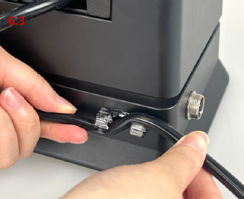
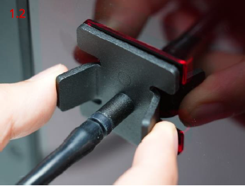
Note: The small metal flange of the feeding tube has a registration pin that needs to correspond to the port in the rear cover of the DF2 (as shown in the red boxes in image 1.1). When the registration pin is aligned, the metal flange should be able to be pressed flush against the acrylic cover (as shown in image 1.2). This step is imperative to ensure that the resin feeding tube is secured properly.
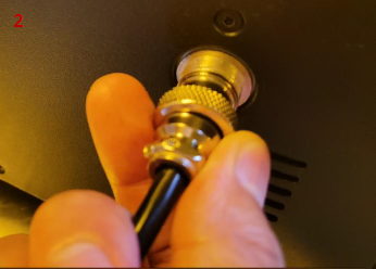
Connect the other end of the connection cable to the connection port for the auto-feeding station on the back of the DF2.
Note: The notches on the connectors need to be aligned.
The location of the connection port for the auto-feeding station can be found in the section of Lists of Parts in Chapter B in the "Raise3D DF2 3D Printer User Manual".
The DF2 auto-feeding station is now completely integrated with the DF2.
Before printing: The DF2 will calculate the amount of resin needed for the model based on the print file. Once the value is determined, the DF2 will send a signal to the auto-feeding station to fill the resin tank. If the amount of resin required exceeds the capacity of the resin tank, the auto-feeding station will fill the resin tank to the max first, then the print will begin.
During printing: The liquid level detector will monitor how much resin is left in the resin tank. Once a minimum level is reached, the auto-feeding station will automatically add appropriate amount of resin to complete the current task.
If there is an insufficient amount of resin left in the resin container, the users will be prompted on the printer’s screen that the resin container will need to be replaced. Please refer to the step 5.1 in the section of Assemble the DF2 Auto-Feeding Station to remove the resin container cap with straw from the former resin container and install it onto the new one.
Notes:
1) When removing the resin container cap with straw, please be mindful that excess liquid resin will drip from the straw. It is recommended to use the resin-resistant tray included with the DF2 in order to catch any excess resin and keep the environment clean.
2) When the viscosity of the liquid resin is too high to support auto feeding, the DF2 will prompt "This resin does not support automatic feeding, please feed it manually.”
B.3 Replace the Liquid Resin with Another Type
If you need to replace the liquid resin with another type, please replace the following items before assembling the auto-feeding station, and then reassemble the auto-feeding station according to the steps described above in the section of Assemble the DF2 Auto-Feeding Station.
1.Resin container x1
2.Resin feeding tube x1
3.The pump in the supporting platform x1
4.Resin container cap with straw x1
5.Feeding hose (long) x1
6.Pump hose (short) x1
The replaced resin feeding tube needs to be inserted into the sealing cap to avoid resin overflow as shown in the red circle in image 2. The replaced items need to be cleaned until completely free of residual resin and properly stored in the accessory box to avoid ultraviolet radiation, and thus still be in working condition for future use.
Note: If any of the above items for the auto-feeding station are not replaced before using another type of the liquid resin, it may affect the printing effectiveness or the auto-feeding process.
