
[ Manual N2&N2 Plus - How to Replace Back Shaft –V1.0 ]
1. Turn the printer off.
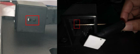
2. Unscrew the silver cross screws shown in figure 1.
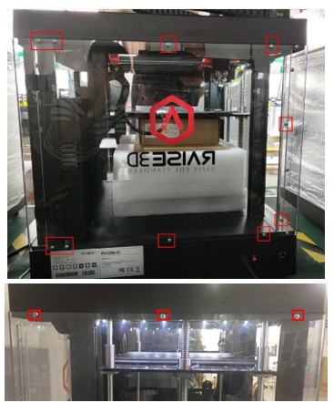
3. Unscrew the 8 black screws on the top cover shown in figure 2.
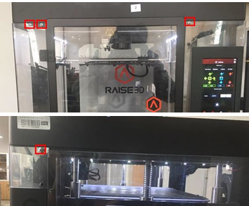
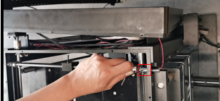
4. Loose the USB cable via a straight screwdriver, this cable is fixed by glue shown in Figure 3.
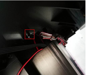
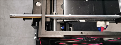
5. Remove the chain towing fixed screws shown in figure 4.
6. Remove the ties which are under the top cover. Now you can lift the top cover up.
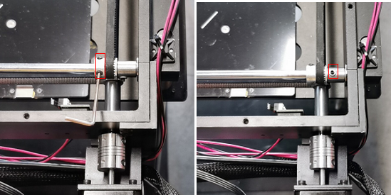
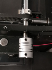
7. Find the Y motor which is on the rear-right side of the printer and you will see there is a shaft coupler. Then unscrew the two grub screws and another two round head screws. (the couplers on your machine may have 4 grub screws and no round head screws)
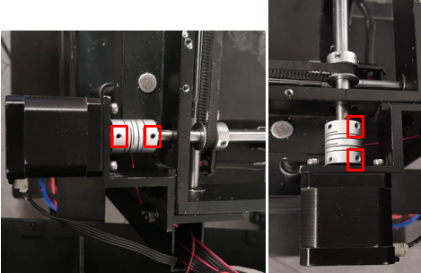
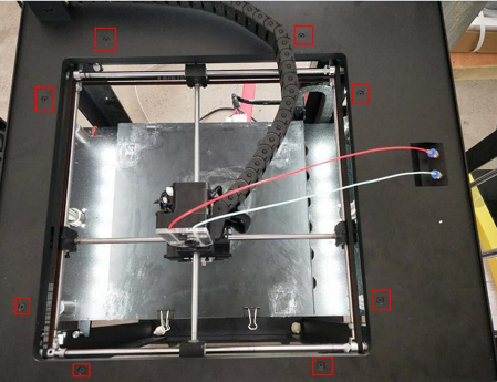
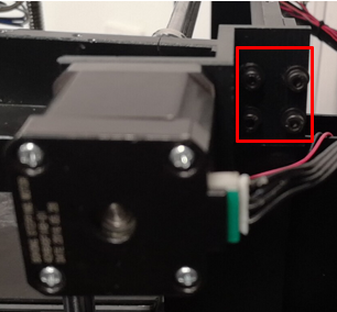
8.Remove the Y motor and its support frame. Firstly, you have to unscrew the four round head screws shown in figure 5. And please note that you have to hold the motor at the same time in case the motor drops on the ground.
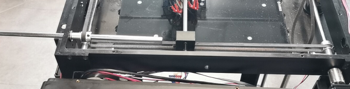
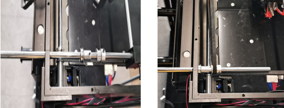
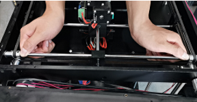
9. Loosen the screws in the belt pulleys and spacer collets on the left side.

10. Loosen the screws in the belt pulleys and spacer collets on the right side.
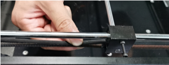
11. Pull the back shaft out from the sliding block.
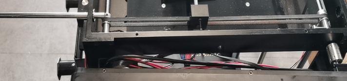
12. Pull the back shaft out from the printer.
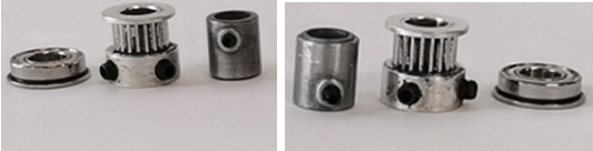
13. Seperate the spare parts.
14. Push the new shaft into the original position.(Note: Face the flat surface towards the filament spool)
15. Collect the belt pulleys and spacer collets on the right side and put them back to the new shaft before it reaches the sliding block. Wrap the rear belt onto the belt pulley.
16. Collect the belt pulleys and spacer collets on the left side and put them back to the new shaft after it reaches the sliding block. Wrap the rear belt onto the belt pulley.

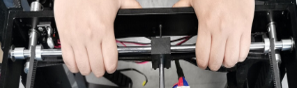
17. Push the bearing into their corresponding holes while pulling tension into the belts. Push the shaft leftward till you can’t push it anymore .
18. Tighten the screws of the right spacer collets by pushing the belt pulleys to their ends.
19. Tighten the screws of the left spacer collets by pushing the belt pulleys to their ends.

20. Push the belt pulleys to their ends.
21. Pinch the belt to feel its tension.
If the belt tension is qualified ,please tighten the screws on them.
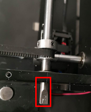
22. Rotate the back shaft until the flat surface faces upwards.
23. Put the shaft coupler to the end of the back shaft .
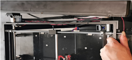
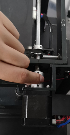
24. Insert the Y motor into the coupler(The flat surface faces upwards.)
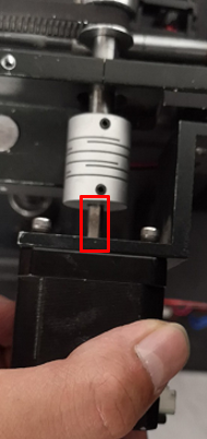
25. Pre- tighten the two screws which hold the support frame until you can’t move the Y motor easily. (When pre-tightening the screws, the motor should be held by hand to prevent the coupling from breaking)

26.Check the motion of the Y shaft coupler by holding it with your finger and pushing it forward and backward.
27. If the coupler does not slide back and forth easily ,please loosen the screws of the support a little until the motor moves to the exact position, which is aligned to the back shaft. Only after the coupler can move smoothly when you use your fingers to drag it forward and backward, can you then pre-tighten the screws in the support frame.
Check the motion of the Y coupler again and carry out step 8 until the Y coupler motion is very smooth.
28. Move the Y coupler to the position where faces its front edge

Ensure the two grub screws in the Y coupler are against the flat surfaces of the Y motor shaft and back shaft. Or reinstall the Y coupler.
29. Tighten the screws in the Y coupler. Install the lid and put the PC cover back.
[ Manual N2&N2 Plus - How to Replace Back Shaft –V1.0 ]
END
