
[ Manual N2&N2 Plus - How to Replace the X motor - V1.0 ]
1. Turn the printer off.
2. Remove the sliver cross screws as Figure 1.
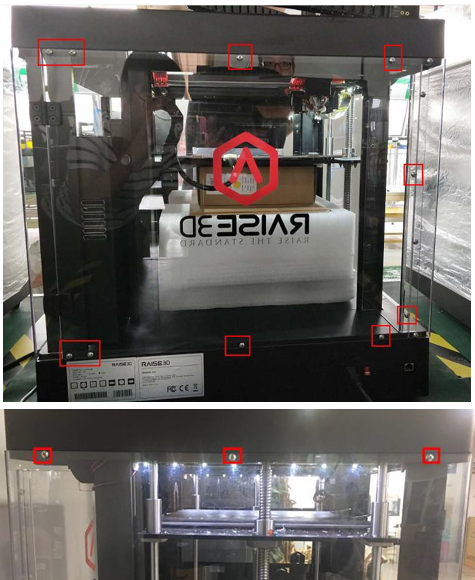
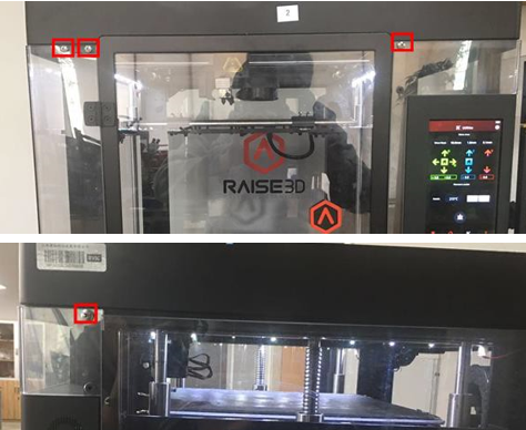
Figure 1 Remove the screws.
3. Remove the 8 black screws on the top cover as Figure 2.
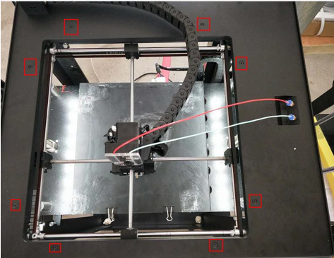
Figure 2 8 Screws on the top cover.
4. Loosen the USB cable with a flathead screwdriver, this cable is held in place by glue as shown in Figure 3.
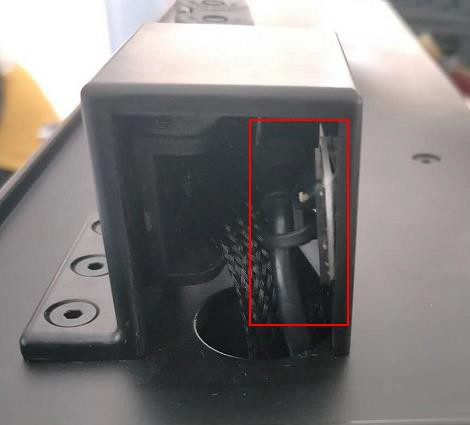
Figure 3 USB cable.
5. Remove the chain retaining screws as Figure 4.
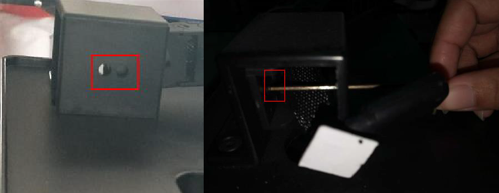
Figure 4: Chain retaining screws.
6. Remove the cable tie located under the top cover. Lift the top cover.
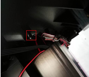
Figure 5 Remove the cable tie located under the top cover.
7. Find the X motor near the coupling on the rear left side of the printer. Then remove the two flat head screws and two round head screws (some models may have 4 flat head screws instead of round head screws)
8. Disassemble the X motor and its support frame. First remove the four round head screws, as shown in Figure 6.
Note: Be sure to hold the motor firmly to prevent it from falling.
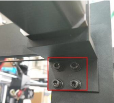
Figure 6 The four hex head screws retaining the support.
9. Remove the four screws which hold the motor mount and X motor with a 3mm hex wrench.
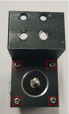
Figure 7 Separate the support frame and the X motor.
10. Assemble the new X motor and the support frame together as the figure below. (Place the slot up and place the support the frame to the left.)
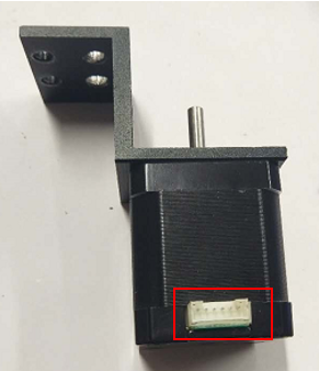
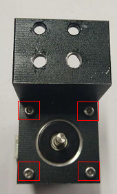
Figure 8 Tighten the screws.
11. Rotate the left shaft until the flat surface faces upwards.
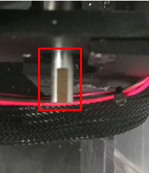
Figure 9 Rotate the left shaft.
12. Align the shaft coupler to the end of left shaft.
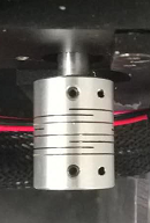
Figure 10 Align the shaft coupler.
13. Insert the X motor into the coupler (with the flat surface upwards).
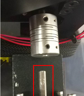
Figure 11 Insert the X motor into the coupler.
14. Pre-tighten the two screws retaining the support frame until the motor cannot rotate easily.
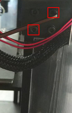
Figure 12 Pre-tighten the two screws.
15. Press the X-axis coupler with your fingers, and then push it forward and back to check the movement of the X-axis coupler.
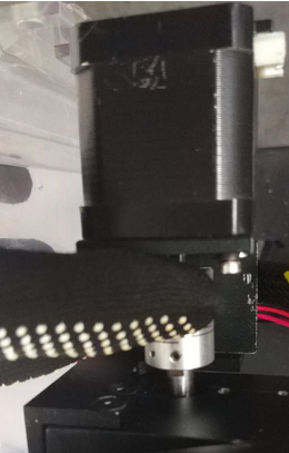
Figure 13 Check the movement of the X-axis coupler
16. If the coupler cannot slide back and forth easily, loosen the screws of the bracket slightly until the motor moves to the correct position (aligned with the left shaft). Only after the coupler moves smoothly, can the screws in the support frame be pre-tightened.
Check the movement of the X coupling again, and then perform step 17 until the X coupling moves smoothly.
17. Move the X coupler to a position where the front end is 1 to 2 mm away from the front end. to the position where its front edge is 1 to 2 mm from front edge.
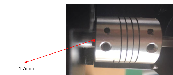
Figure 14 Move the X coupler.
18. Make sure that the two flat-head screws in the X coupling are close to the surface of the X motor shaft and the left shaft. Tighten the screws in the X coupler. Reinstall all remaining parts.
[ Manual N2&N2 Plus - How to Replace the X motor - V1.0 ]
-END-
