
[ Manual N2&N2 Plus – How to Replace the Y motor – V1.0 ]
1. Turn the printer off.
2. Remove the silver cross screws shown in Figure 1.
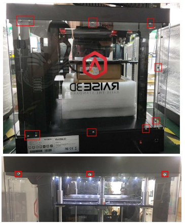
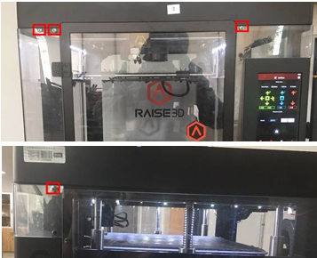
Figure 1 Remove the screws.
3. Remove the 8 black screws on the top cover shown in Figure 2.
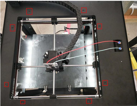
Figure 2 Remove 8 screws on the top cover.
4. Loosen the USB cable with a flat screwdriver, and fix the cable with glue, as shown in Figure 3.
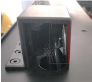
Figure 3 USB cable.
5. Remove the chain retaining screws shown in Figure 4.
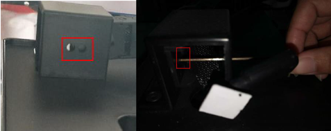
Figure 4: Chain retaining screws.
6. Remove the ties which are under the top cover. Now you can lift the top cover up.
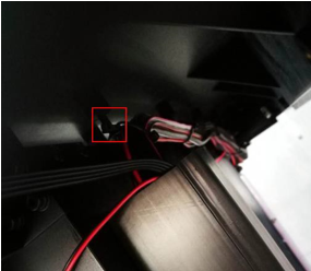
Figure 5 Remove the cable tie that binds the cable.
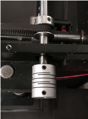
7. Find the Y motor on the back right side of the printer, you will see a shaft coupler. Remove the two flat head screws and the other two round head screws. The couplers on your machine may have 4 flat head screws, without round head screws.
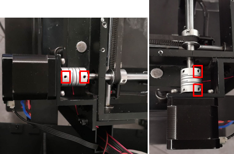
Figure 6 Two screws on the shaft coupler.
8. Dismantle the Y motor and its support frame. First, you have to remove the four round head screws shown in Figure 7.
Note: Please hold the motor at the same time in case the motor drops on the ground.
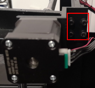
Figure 7 Remove the four round head screws.
9. Remove the four screws retaining the motor bracket and the Y motor together with a 2.5mm hex wrench.
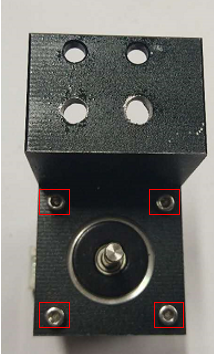
Figure 8 Separate the support frame and Y motor.
10. Assemble the new Y motor and the support frame together in Figure 9. Move the slot to the left and the support frame to the right.
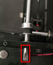
Figure 9 Assemble the new Y motor and the support frame.
11. Rotate the back shaft until the flat surface faces upwards.
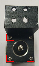
Figure 10 Rotate the back shaft.
12. Put the shaft coupler at the end of the back shaft.

Figure 11 Put the shaft coupler at the end of the back shaft.
13. Insert the Y motor into the coupler with the flat surface facing upwards.
Insert the Y motor into the coupler(The flat surface facing upwards.)
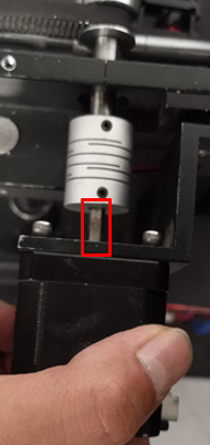
Figure 12 Insert the Y motor into the coupler.
14. Pre-tighten the two screws that retain the support frame until the Y motor cannot be easily moved. When tightening the screws, please hold the motor with your hands to prevent damage to the coupler.
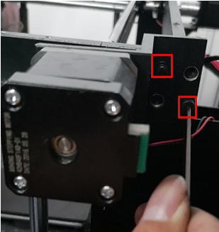
Figure 13 Pre-tighten the two screws.
15. Check the motion of the Y shaft coupler by holding it with your finger and pushing it forward and backward.
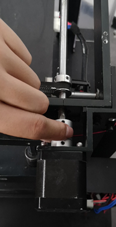
Figure 14 Check the motion of the Y shaft coupler.
16. If the coupler does not slide back and forth easily, please loosen the screws of the support a little until the motor moves to the exact position, which is aligned with the back shaft. Only when the coupler can be moved smoothly by dragging the coupler back and forth with fingers, can the screws in the support frame be pre-tightened.
Check the movement of the Y coupling again, and then perform step 17 until the movement of the Y coupler is very stable.
17. Move the Y coupler so that it faces the front edge.
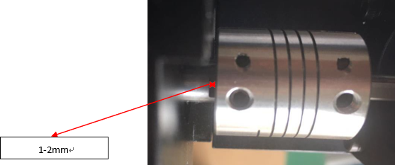
Figure 15 Move the Y coupler.
18. Make sure that the two grub screws in the Y coupler are against the flat surfaces of the Y motor shaft and the back shaft. Or, please readjust it. Tighten the screws in the Y coupler and reinstall all parts.
[ Manual N2&N2 Plus – How to Replace the Y motor – V1.0 ]
-END-
