
[ Manual N2&N2 Plus - How to Upgrade the Extruder –V1.0 ]
1. Unload Filament
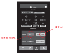
In the 'Utilities' tab, verify that the temperature is set for your material. (215 C for Raise3D PLA)
Use the arrows to adjust the temperature if required. Press the "Unload” button to begin.
The printer will begin to heat up to the designated temperature. Once the temperature is reached the Unload button will become available.
Press Unload to withdraw the filament.
Power off the printer once unloading has been completed.
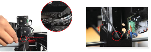
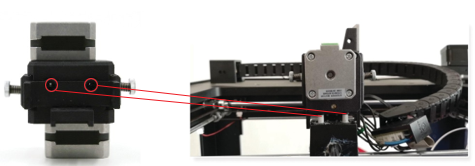
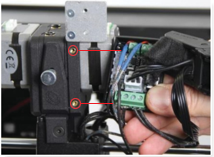
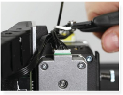
2. Unplug Cables

Unplug the two connectors marked in the image below.
If you have a dual extrusion model, use tape to mark the right extruder motor (lower position). This will help
distinguish the cables when it comes time to connect the new extruder.
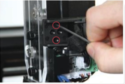
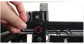
3. Remove Screws
First, remove the hex screws on the left and right sides of the extruder head with a 2.5mm hex
wrench. There will be 1 screw on each side.
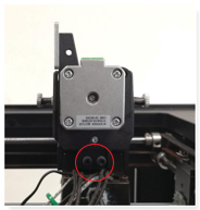
Then, remove the two screws on the back side of the extruder. They are located underneath the two motors.
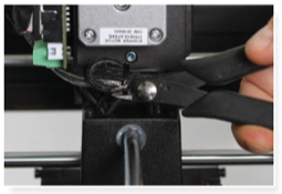
4. Remove Screws (Cont.)
Remove the two screws that affix the cable chain with a 2.5mm hex key.
Lastly, remove the two fixing screws and cover from the extruder board.
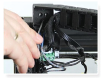
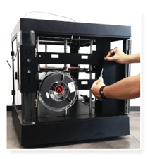
5. Remove the Extruder
Remove the original extruder by pulling straight up.
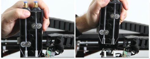
6. Attach New Extruder
Locate the openings at the bottom of the extruder and insert the PTFE tubes into the mounting holes. Push the extruder all the way down until it is securely seated.
7. Insert Screws
Insert the original screws to the left and right of the extruder head. Do not tighten these fully.
Install the 2 original rear screws with the 2.5mm hex wrench. Do not tighten the screws fully.
Once the 4 screws from this step are installed, take turns evenly tightening each one.
Be careful not to overtighten these screws as the tension can create cracks in the material.
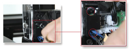
8. Connect the Extruder Board
Attach the extruder board with the new holder.
Note: The two screws are different sizes.
The upper screw is an M3 while the lower is M2.5
9. Connect the Cable Chain
Use the original screws to connect the cable chain.
10. Connector Wiring

If you have a dual extruder machine, select the wire that was not marked with tape from step 2.
Remove the two leftmost wires.
Use a sharp tool to lift the small plastic tab on the connector and gently pull the crimping contact out of the housing with your hand.
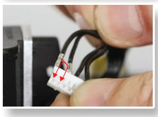
Reverse the position of these two wires and reinsert them into the connector
11. Motor Wiring
Attach the unmarked cable to the port on the back extruder.
Attach the marked cable to the port on the front extruder.
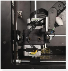
12. Cable Management
Use cable ties to secure loose wires. Gather the motor wires on the top of the extruder and secure them.
Cut off the cable tie excess.
Secure the wires underneath the motors with another cable tie.
Cut off the cable tie excess.
Software Configuration
The following section will show how the E-Step value can be adjusted directly on the printer.
The E-Step value tells the controller the number of steps (micro steps) that are needed to extrude 1mm of filament. The new extruder has a different drive gear diameter and gearing ratio and must be adjusted to extrude the proper amount of material. In return, the increased step value means that the extruder will feed the filament with higher precision.
13. Open Settings
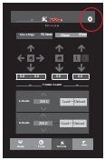
In the 'Utilities’ tab select the settings icon in the upper right hand corner.
Select: More Settings > Hardware > Step Per Unit. > E Steps Per Unit.
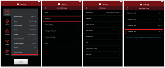
14. Change Value
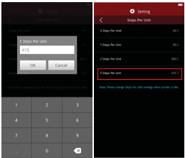
Change the E Step value to 415 and press OK.
Verify that the value has correctly been changed in the previous menu.
Electronic Configuration
The installation of the new extruder also requires that the stepper driver is adjusted. The current motors are smaller and require lower current than the original motors. Without this adjustment, there is a risk that the motors can overheat and become damaged.
To complete this adjustment, you will need:
-A Multimeter
-A Sharp tool
15. Access Electronics
Use a hex wrench to remove the electronics cover. If your model does not use hex bolts, use a sharp tool to pop open the cover.
16. Measure Vref Voltage
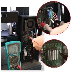
Touch the black probe to the lower screw of the green terminal.
Touch the red probe of the multimeter to the screw of the stepper driver potentiometer located in the upper left.
The multimeter should now display the Vref Voltage of the driver.
[ Manual N2&N2 Plus - How to Upgrade the Extruder –V1.0 ]
End
