[ Manual Pro2 Series - 020 Endstop Limit Switch Board Installation Instruction-V1.0 ]
1. The Locations of Endstop Boards

2. Power Off
Power off the printer.

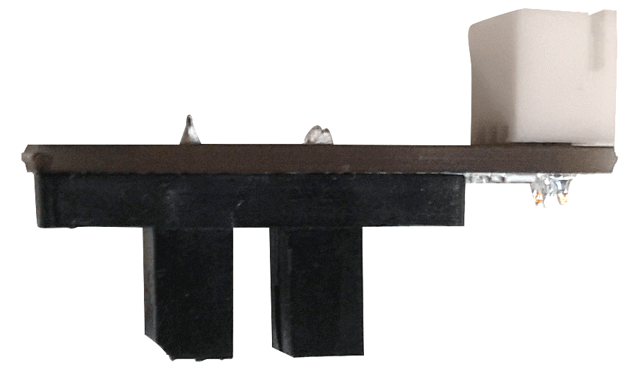
3. Remove the Z-Endstop Limit Switch Board
- The steps of replacing Endstop Board are similar for different directions. We will use Z direction here as reference.
- Unplug the cable on Z-Endstop Board.

- Remove the two fixing screws marked in image below and take the old Endstop Board off with casing.

4. Reinstall Z-Endstop Limit Switch Board
- Fix new Z-Endstop Board to original position with two fixing screws removed before.
- Plug the cable back onto the Board.
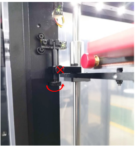
5. Bed positioning
- As replacing Endstop Board may affect Z home height, it is better to apply a height calibration before printing. For the other two directions, calibration is not a necessary step.
- Raise the Z limit pin by rotating the bottom screw counter clockwise from a top down perspective.
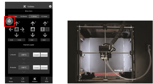
- Heat both hotends to 180c or to the temperature of loaded filament from the home screen.
- Activate the left nozzle by selecting it in the utilities screen and pressing the up or down arrows
- In the Utilities tab, select the Z-Axis Home button to move the bed into the origin position.

6. Extruder Positioning
- Disable the motor with the ‘Disable Motor’ button. This will allow you to freely reposition the extruder by hand.
- Move the extruder head along the rods into the center position.
When physically moving the extruder, avoid touching high-temperature components. Perform all motions via the upper section of the extruder head.
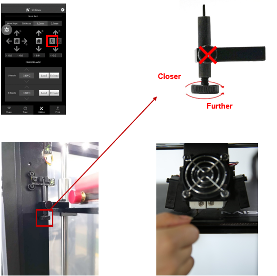
7. Left Nozzle Calibration
- Use the feeler gauge (included in printer toolkit) and place it underneath the left nozzle.
- To adjust the nozzle height, rotate the large thumbscrew as depicted in the diagram.
DO NOT adjust the small side-mounted screw.
- Home the Z-Axis, then verify the new height using the feeler gauge.
- Homing is required each time the knob is adjusted.
- Repeat until desired result is achieved.
Adjustments should be made incrementally. Changes in height will NOT be visible until after homing.
[ Manual Pro2 Series - 020 Endstop Limit Switch Board Installation Instruction-V1.0 ]
-END-

