
[ Manual Pro2 Series - 027 Heated Bed Power Supply Cable Replacement Guide-1.0 ]
① Zip ties
② Flat head screw driver
③ Spatula
④ Flush cutter

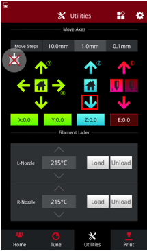
1. Press the Z home button. Once bed completely homes, press Z value button in Utilities page and lower the bed to the proper position until a screw driver can reach the terminal block.(Note: You can set the height to 50-100mm.)
2. Turn off power and remove back panel by removing the silver Philips head screws.
3. Remove the heated bed cable socket with a 3mm flat head screwdriver.

4. Open the buckles of the cable chain with a small flathead screwdriver. Unplug heated bed sensor.
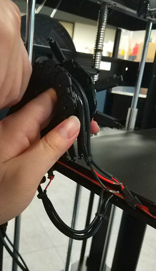
5. Carefully lay the printer down on the side opposite the filament door and open the cover of motion controller board.(Access the motion controller board by removing the panel with the lightning bolt on it).

6. Remove the heated bed cable with a flat head screw driver

7. Remove plastic bellows underneath the printer and cut the zip ties. Pull out the heated bed cables (the thickest one among the wires). In some cases it may be difficult to access the wires without removing the bottom panel.
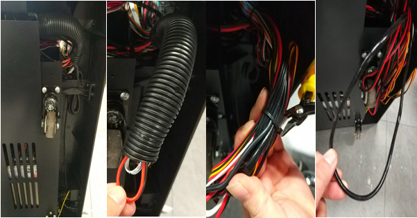
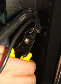
8. Cut every zip tie that attaches the heated bed cable along the frame of printer. Remove old cable and replace with a new one.
9. Attach the new cable to the harness with zip ties.
10. Install the new one to the motion controller board.
Note: The Red Wire is inserted into positive and the black one goes to the negative.
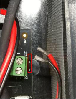
11. Install the heated bed cable wires into the power socket holes and tighten the screws with a 3mm flat head screwdriver. Close the cable chain and plug the sensor cable together.
Note: Do not insert down to wire insulation or it may cause electrical short ;the red (power) wire should align with corresponding red wire at each side of power socket.

[ Manual Pro2 Series - 027 Heated Bed Power Supply Cable Replacement Guide-1.0 ]
