
[ Manual Pro2 Series - 028 Hotend Installation Instruction-V1.0 ]
1. Drop the build plate
• Lower the Z-Axis platform by using the onboard touchscreen. This menu can be found in the Utilities tab.
• Lower the plate until you have enough clearance to comfortably maneuver tools within the area (150-250mm)
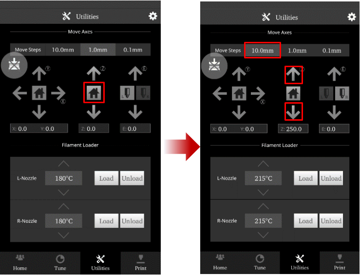
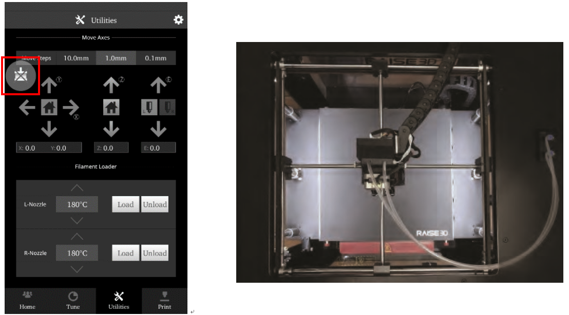
2. Unload filament
• In the ‘Utilities’ tab, verify that the temperature is set for your material. (215℃ for Raise3D PLA)
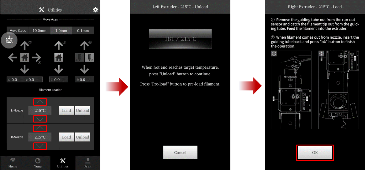
• Use the arrows to adjust the temperature if required. Press the ‘unload’button to begin.
• The printer will begin to heat up to the designated temperature. Once the temperature is reached the Unload button will become available.
• Press Unload to withdraw the filament.
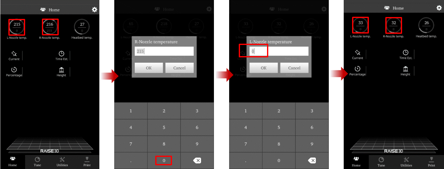
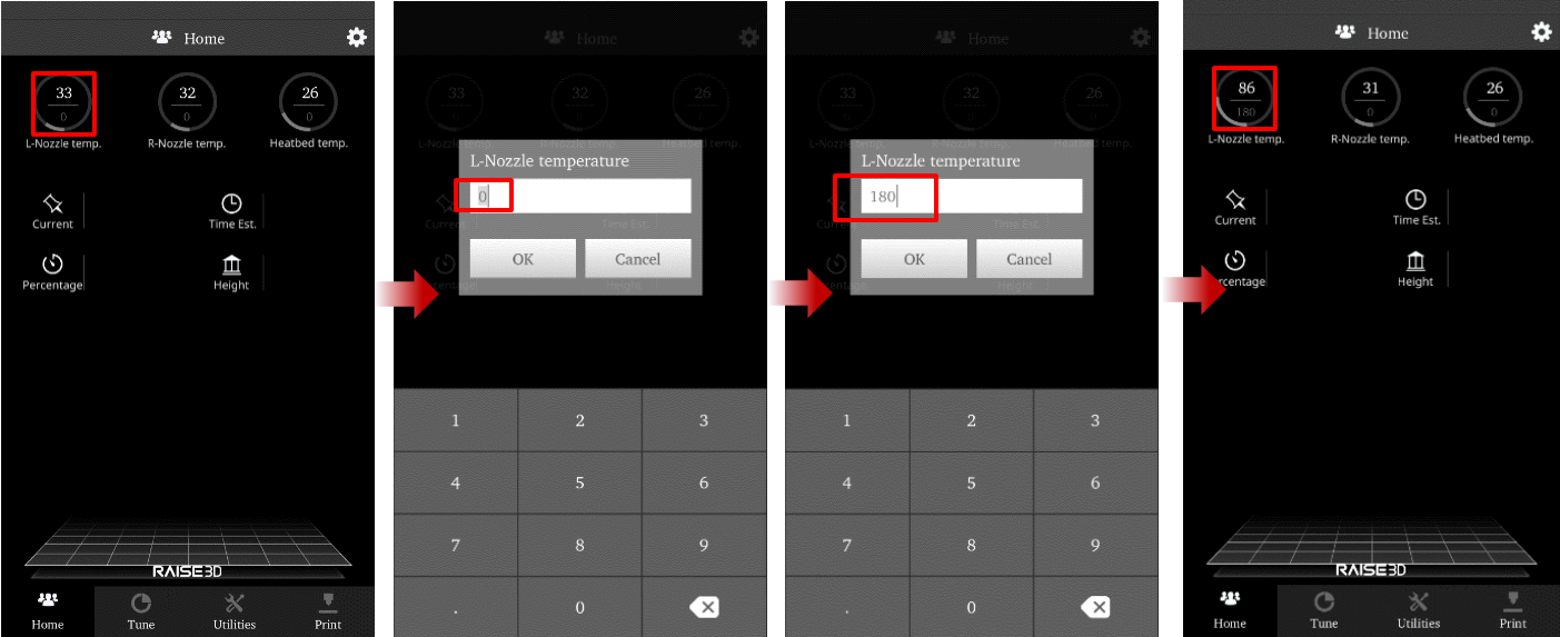
3. Cool down
• Open the ‘Home’ tab, and click on the nozzle temperature. In the new window, set the temperature at 0, and press OK. Do this for both nozzles.
• Allow the components to cool down completely before continuing.
• When the extruders reach an ambient temperature, power off the printer.
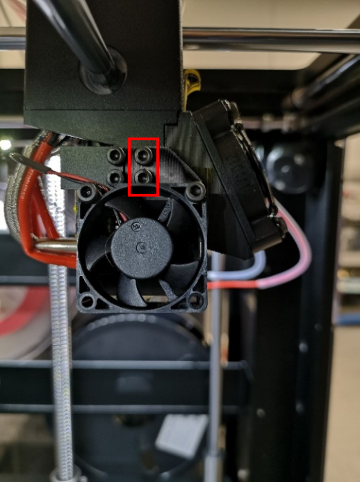
4. Remove Cooling Fan
Remove the two fixing screws of the cooling fan with a 2.5mm hex wrench.
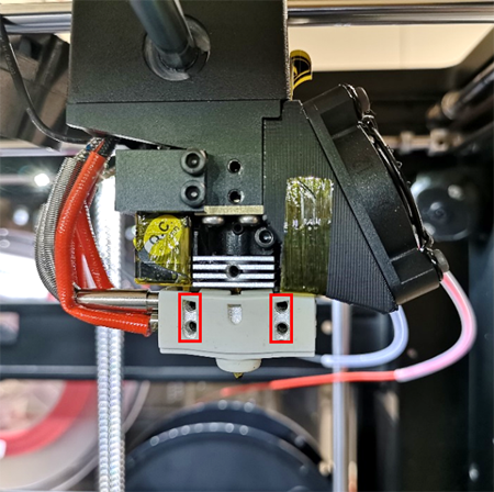
5. Remove the hotend
Loosen the 4 set screws inside the heating block. This will release the hotend from the wiring, which will be removed in the next step.
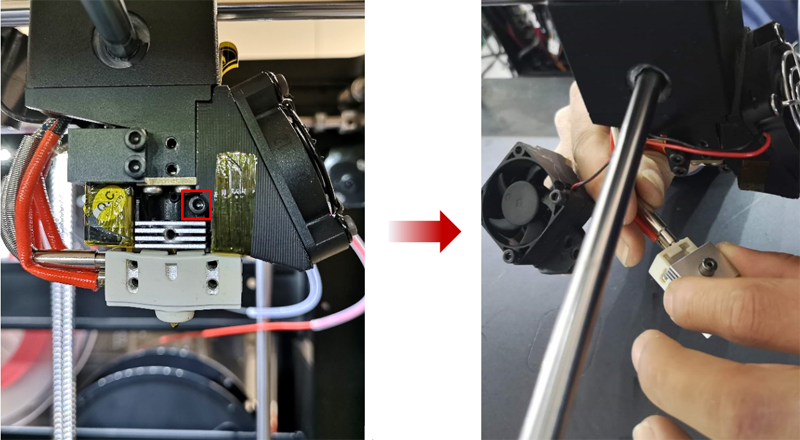
• Loosen the fixing screw to release the hotend from the machine.
• Remove the heater rod and thermocouple wires from the heater block to fully remove the hotend.
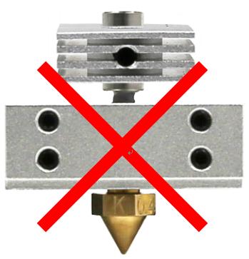
6. Inspect Replacement HotEnd
• To completely replace the hotend, verify that the new hotend is properly adjusted.
• The bottom of the heat sink should lie flush with the bottom of the larger cylinder.

• If the heat sink is improperly positioned refer to the Nozzle Replacement document for additional instructions.
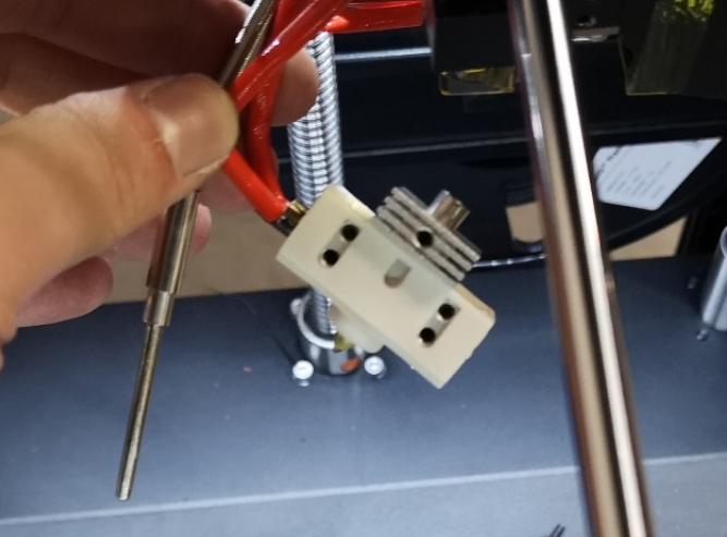
7. Wiring
• Insert the heater rod (Red Wire) into the bottom hole of the heater block. Insert it so that it reaches the other end of the heatblock and secure into place with the two set screws.
• Insert the silver thermocouple into the upper hole on the heater block.
• Secure it in place with the two set screws.
8. Install hot end
• Insert the hotend and push it all the way up.
• Secure it by tightening the clamping screw.
If replacing multiple hotends, repeat steps 4-8 with the second hotend before continuing to the alignment procedures.

9. Adjust the other Hotend
• Loose the fixing screw marked in red with 2.5mm hex wrench.

• Insert the hotend and push it all the way up.
• Secure it by tightening the fixing screw.
10. Bed positioning
Nozzle height calibration bellow
• Power on your unit.
Cooling fans will not be attached by this stage. Exercise caution when operating around spinning parts.
• In the Home tab of the touchscreen, select the Left nozzle, and set the temperature to 180. This will ensure that the left nozzle is enabled and in the proper position.
• In the Utilities tab, select the Z-Axis Home button to move the bed into the origin position.
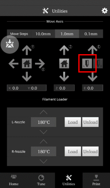
11. Extruder Positioning
• Disable the motor with the ‘Disable Motor’ button. This will allow you to freely reposition the extruder by hand.
• Move the extruder head along the rods into the center position.
When physically moving the extruder, avoid touching high-temperature components. Perform all motions via the upper section of the extruder head.
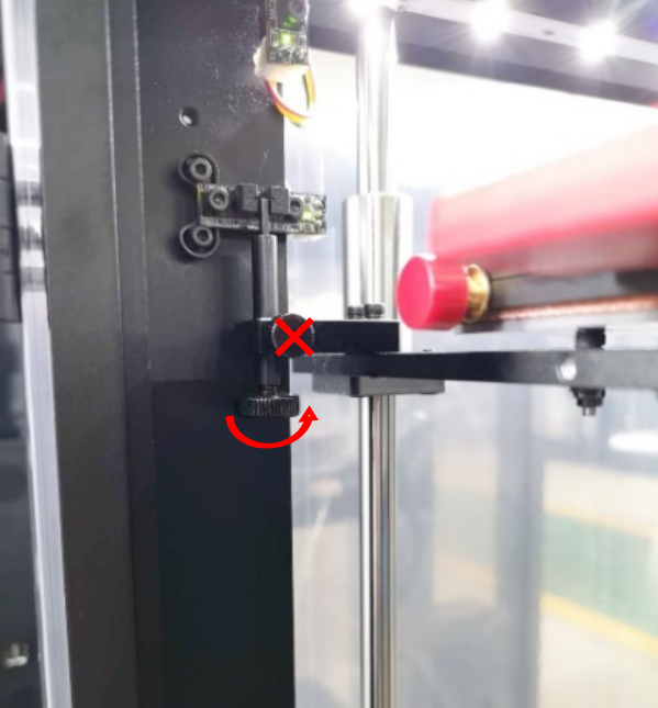
12. Left Nozzle Calibration
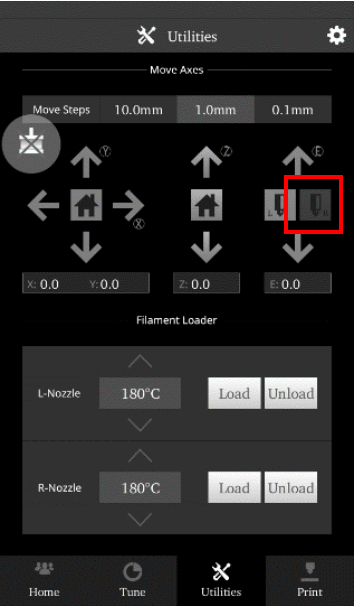
Select the Left Nozzle Icon, and press the down arrow to ensure the left nozzle is enabled.
• Use the feeler gauge (included in printer toolkit) and place it underneath the left nozzle.
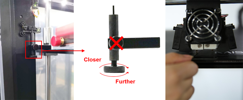
To adjust the nozzle height, rotate the large thumbscrew as depicted in the diagram.
DO NOT adjust the small side-mounted screw.
• Home the Z-Axis, then verify the new height using the feeler gauge.
• Homing is required each time the knob is adjusted.
• Repeat until desired result is achieved.
Adjustments should be made incrementally. Changes in height will NOT be visible until after homing.
13. Right Nozzle Calibration
* The left nozzle should and bed should already be in proper position before continuing.
• From the home screen, heat the right nozzle to 180, Enable the right nozzle by pressing the icon, then the down arrow.
• Once the nozzle is enabled, set the temperatures to 0, and allow them to cool completely before continuing.
• Once the hotend has cooled completely, Inset the feeler gauge under the right nozzle and check for proper height.
• If the nozzle needs further adjustments, loosen the setting screw, and manually move the hotend until it is able to come in contact with the feeler gauge.
DO NOT adjust the bed height. Adjusting the bed will affect the left nozzle, which will require recalibration starting from step 9.
• Tighten the screw into this position.

• When the nozzle height is properly calibrated, power your unit off and re-install the cooling fans.
[ Manual Pro2 Series - 028 Hotend Installation Instruction-V1.0 ]
-END-
