

Summary and Notes:
In this guide, we will cover the best practices for creating a level bed plane, relative to the nozzle.
It is important to note that some portions of the procedure may be necessary to repeat for honing in on more favorable results.
TOOLS
1) 0.2mm Feeler Gauge
2) 2.5mm Hex Wrench/Allen Key
3) 5.5mm Socket Tool
4) Tweezers
Note: Except for a 5.5mm socket tool, these tools should be included in the accessories kit box that was originally packaged with the printer.

Let’s get started:
Step 1.) Ensure the Left nozzle is in the lowered position. Prepare the printer for nozzle shifting.
Press the Home tab on the touchscreen, and set the nozzle temperature for both the left and right nozzle to 180℃ if filament is unloaded from both sides. This is the default minimal shifting temperature the printer will allow for the nozzle shifting movement to occur.
If filament is loaded on either side, set an appropriate minimum melting temperature for that nozzle. Rigid filament will impede the movement of the nozzle-shifting mechanism.
Press L-Nozzle temp. display to open the number pad to input a target temperature.
Press OK to accept the target temperature. The nozzle should begin heating.

In our example above, the left nozzle temperature was set to a sufficient minimum melting temperature for our example filament loaded in the left side.

[ ! ] Repeat the heating process for the right nozzle.
When both nozzles reach their target tempertures, the status rings around the nozzle temperatures should turn green, indicating measured temperature matches target temperature.
Step 2.) Execute the command to shift the Left nozzle to a lowered position.
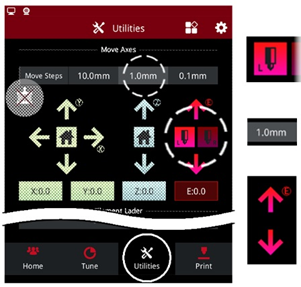
Press the Utilities tab on the touchscreen, and press the red L-nozzle icon to toggle-select the left nozzle. ( Note: The toggle-select alone will NOT shift the nozzles )
Ensure Move Steps is set to a low value, like 1.0mm, especially if filament is loaded in either side.
Press the red down arrow to command a nozzle-shifting movement, which would extrude 1.0mm of filament.
( Note: The red up arrow will retract filament )
Step 3.) When the left nozzle is verified to be in a lowered position, press the Home tab on the touchscreen and set the nozzle temperature for both the left and right nozzles to 0℃to cool the nozzles. Allow both nozzles to cool to relative room temperature.

Note: If filament was extruded, or happens to be protruding/oozing from the nozzle opening, it is recommended to carefully clear any filament debris at the tip of the nozzle using tweezers for careful precision.
Debris present at the nozzle tip could negatively influence our results when using the feeler gauge.
When using the feeler gauge, it is important that the tool makes direct contact between the nozzle tip and the build plate surface when placed between these two points.
Step 4.) Press the Utilities tab on the touchscreen and press the stepper motor icon with an “X” to disable the stepper motors. A message should state “motors have been disabled”.

( Note: Pressing any X/Y/Z arrows, Home icons, or starting .gcode should automatically enable the motors for the printer to function normally )

With the stepper motors disabled, the printhead should move freely.
It is recommended to securely hold the printhead at the block with the cross-rods for manually positioning the printhead.
Step 5.) Carefully guide the printhead to the front-left corner of the bed, while observing the nozzle’s distance from the build surface. The nozzle should not collide with the build surface while the printhead is being positioned.
[ ! ] If the nozzle may collide with the build surface, please reference Step 8

Step 6.) Ensure the bed platform is raised to its zero coordinate Home position of Z0.
While still on the Utilities tab at the touchscreen, select the blue Z-Axis Home icon to raise the bed platform to its Home position.

It is important that we use this Home position for the Z-axis to establish and verify a proper nozzle and bed distance relationship for successful 1st layer adhesion of the filament to the build surface (BuildTak printing surface material).
[ ! ] Note: This nozzle / bed distance relationship at the Home position is commonly referred to as the Z-offset distance.
Step 7.) Carefully slide the 0.2mm feeler gauge between the Left nozzle tip and the build surface. It is important that the feeler gauge is flat against the build surface.

[ ! ] The process of using the feeler gauge exclusively relies on creating a reliable and repeatable subjective tactile feedback between the nozzle tip and build surface.
It will be important to establish referenceable tactile feedback to attempt to replicate at different points on the build surface for the purpose of establishing a level build surface.
[ ! ] Adjusting the Z-offset for the purpose of this bed leveling calibration may be necessary if the feeler gauge can not:
- Be inserted between the nozzle tip and the build plate surface
- Provide reliable and repeatable tactile friction to reference for repeating at the remaining 3 corners of the bed’s surface.
If there is no issue with the current Z-offset, please skip to Step 9
Step 8.) Adjusting the Z-offset is achieved by rotating the larger thumbscrew to influence the pin height on the thumbscrew assembly, which is located at the front-left corner of the bed.

( Note: Pressing the blue Home icon will command the bed platform to travel upwards. The pin is used to activate an optical sensor that electronically commands the printer to stop raising the bed platform upwards toward the nozzles.
When the pin rests at the sensor, the bed platform coordinate will reset to Z:0.0, its Home position )

[ ! ] Any screw height adjustment is recommended in quarter-turn increments.
[ ! ] Thumbscrew instructions are relative to a top-down view of the pin assembly:


[ ! ] After an incremental rotation of the larger thumbscrew on the pin assembly, press the blue Z-axis Home button for the printer to reflect any changes intended to influence the Z-offset / Z-axis Home position.
The bed platform should descend, and slowly raise upwards until the pin rests at the optical sensor, setting the printer’s new Z-offset/Home position.
Step 9.) After establishing referenceable subjective tactile feedback between the nozzle tip and build surface at the front-left corner using the feeler gauge,press the stepper motor icon with an “X” to disable the stepper motors.

With the stepper motors disabled, the printhead should move freely.
It is recommended to securely hold the printhead at the block with the cross-rods for manually positioning the printhead.

Step 10.) Carefully guide the printhead to the front-right corner of the bed, while observing the nozzle’s distance from the build surface.
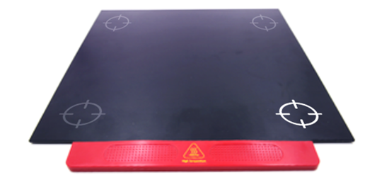
Note: It is recommended to validate a level bed surface by carefully referencing the four corners of the build surface, travelling along the outer perimeter.
[ ! ] If the nozzle may collide with the build surface, stopmoving the printhead and begin the process of adjusting the appropriate screws located at the underside of the bed platform.
Continue to Step 11
Step 11.) The underside of the bed platform contains groupings of two set/grub screws with a nylon locking nut on a center screw within the groups. These groupings of three components help facilitate a careful adjustment mechanism for influencing the bed surface plane.
[ ! ] Please note that a grouping of screws is omitted from the center of the platform by design.

The center screw, using a nylon locking nut, passes through the bottom-most plate and is affixed to the bed platform resting above.
Tightening the nylon nut helps “hold down” the bed platform against the top-side of the two set/grub screws, reducing vertical deviation.
Do not overtighten the nylon locking nuts.

[ ! ] It should only be necessary to adjust the four diagonally oriented groupings of screws
beneath the four corner points of the bed.
To adjust a corner point, first, loosen the center nylon locking nut. Then, carefully “loosening” or “tightening” the set/grub screws will lower or raise the bed plane contact point, respectively, above the grouping. After adjusting the two set/grub screws, secure the nylon locking nut to hold down the bed platform against the top-side of the two adjusted set/grub screws – do not overtighten.


Step 12.) If adjusting a corner point’s height was necessary to create tactile feedbackbetween the nozzle tip and build surface at the front-right corner, use the feeler gauge again to verify if the incremental adjustment was successful.

[ ! ] It may be necessary to repeat this corner adjustment step to ensure a proper height (and expected tactile feedback) is achieved.
Step 13.) Proceed with repeating the feeler gauge process, and underside screw adjustment if necessary, at the rear-right and rear-left corner points of the bed.
If the four corners have been appropriately adjusted, the printhead should be able to be manually moved around the perimeter of the bed while maintaining a relatively equal distance (of a 0.2mm) between the nozzle and the bed surface.
It is important to note that repeating incremental corner elevation adjustments may benecessary after performing feeler gauge validations at other corners of the bed plane.
[ ! ] Please be mindful that influencing a single corner point elevation may affect an adjacent corner point elevation.
[13.115-EN.1.0.20230510-Pro2 Series-How to Create a Level Bed]
-END-
