
Tools:
① 2.0 mm hex wrench
② 2.5 mm hex wrench
③ Flush cutters
④ Tweezers
⑤ Small Phillips-head screwdriver
⑥ Zip-ties
Steps:
1. Unload the filament from both nozzles.
2. Turn off the printer after the filament is removed and nozzles are cooled to ambient room temperature.

3. Remove the 4 fan retaining screws, using the 2mm hex wrench. Remove the front fan along with the metal protective cover.

4. Carefully disconnect the front fan cable from the Extruder Connection Board.

5. Remove the two retaining screws securing the back cover casing, using the 2mm hex wrench, and remove the cover.

6. Carefully cut the zip-ties retaining the cables; do not damage any electrical wires on the printer.

7. Remove the front cooling fan and its cable from the printhead. Do not discard the fan’s metal protective cover.
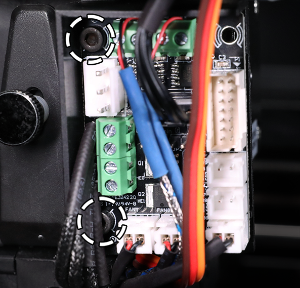
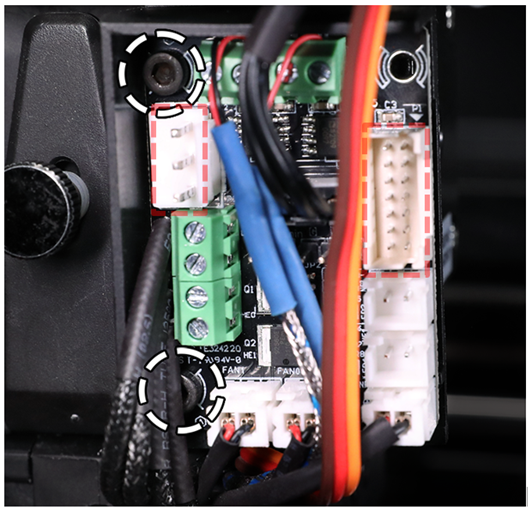
8. Use the 2.5mm hex wrench to remove the two screws, marked in the image below, to more clearly access the heater rod cable and cable terminal. The heating rod cable cannot be removed unless the Extruder Connection Board is removed from the printhead. It can be helpful to temporarily disconnect the 3-pin cable and the colorful ribbon cable for easier access to the board.
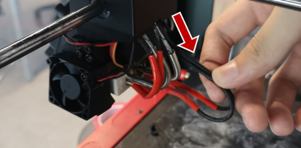
9. Loosen the appropriate small flathead screws on the terminal block, and carefully extract the heating rod cables through the crossrod block, from the underside. With these cables temporarily removed from the cable pathway, navigating the end connector of the replacement front fan should be a more convenient process.

10. With the 2mm hex wrench, affix the protective metal cover and the replacement front fan onto the fan duct, using the 4 retaining screws. Ensure that the fan blade surface with a label is facing inwards, and not visible from the front. The fan’s airflow direction must face inward for optimal hotend cooling performance.

11. Carefully route the replacement fan cable through the underside of the crossrod block, and grab the connector with tweezers (out from the top) to help pass it through the block successfully.

12. Plug the front fan cable into the appropriate terminal connector on the board, marked below.

13. Next, route the heating rod cables back through the crossrod block, and insert the cables back into their terminal. Fasten the terminal screws to securely clamp the cables.
Note: Ensure that there are no exposed wires, or it may cause damage to the printer.

14. Secure the Extruder Connection Board back onto the printhead, fastening the two screws with the 2.5mm hex wrench. Reconnect the 3-pin cable and colorful ribbon cable back into the board.
15. At the back of the printhead, bind the cables together with zip-ties and install the rear cover back over the cables. Fasten the two retaining screws, using the 2mm hex wrench, to secure the cover.

