
Tools:
① Needle nose pliers
② 8mm sleeve
③ Feeler gauge sets
④ 2.5mm hex wrench
⑤Torque wrench (8mm socket)

1. Unload the filament from the extruder where the nozzle needs to be replaced. While this tutorial uses the left nozzle as an example, work with whichever nozzle needs replacing on your printer.
1)Click "Utilities" on the screen to enter the printer control page.
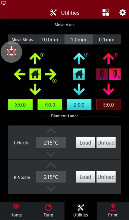
Figure 1 Enter the "Utilities" page.
2)Set the temperature of the left nozzle to the proper unloading temperature. For example, the Raise3D Premium PLA filament is loaded in the left nozzle and its default loading temperature is 215℃. In our demonstration, we set the left nozzle temperature to 215℃.
3)Click the "Unload" button, and the printer will automatically begin to heat. When the printer reaches the targeted temperature, click "Unload". Follow the instruction to unload the filament.
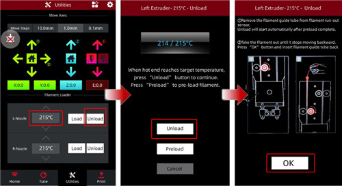
Figure 2 Unload the filament.
4)Gently pull the filaments out of the extruder. Press and hold the metal quick connector to remove the filament guide tube.
1. Enter the “Utilities” page, and click the “Disable Motor” button to disable the motor. Now you can manually move the extruder to the proper position.
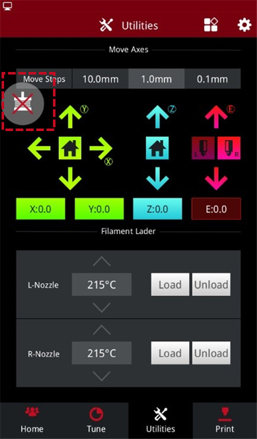
Figure 3 Click “Disable the motor”.
2. Select the Z-axis, then click the up and down arrows to move the build plate to a position suitable for working.
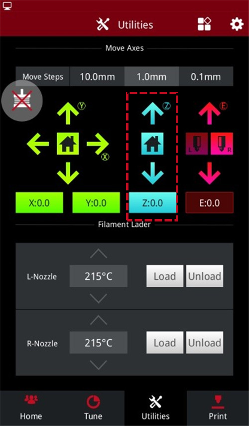
Figure 4 Adjust the height of the build plate.
1. In order to remove the nozzle smoothly, first heat the left nozzle to 180℃-200℃.
1) Select the left nozzle icon on the home page, set the left nozzle temperature to 180℃, and wait for the left nozzle temperature to rise to the specified temperature.

Figure 5 Heat the left nozzle.
2) When the temperature of the left nozzle rises to the specified temperature, turn off the power of the printer.
Note: Do not work on the printer with the power on to avoid personal injury and causing damage to the printer.

Figure 6 Turn off the printer power.
2. You can use a 2.5mm hex wrench to loosen the 4 screws on the model cooling fan and move the fan away.
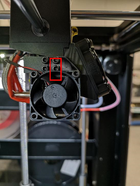
Figure 7 Remove the model cooling fan.
3. Remove the silicone protector from the hot end.
Note: At this time, the hot end is still very hot, be careful of scalding.
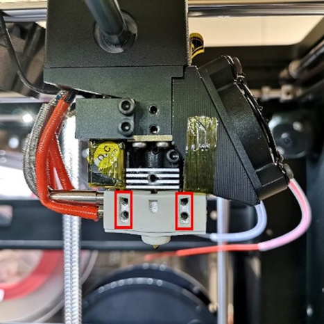
Figure 8 Remove the silicone protector from the hot end.
4. Hold the heating block with needle-nose pliers to prevent the heating block from moving. Then cover the left nozzle with an 8mm sleeve. Turn the sleeve clockwise to loosen the nozzle with the sleeve.
Note: The heating block and nozzle are still hot, be careful of burns.
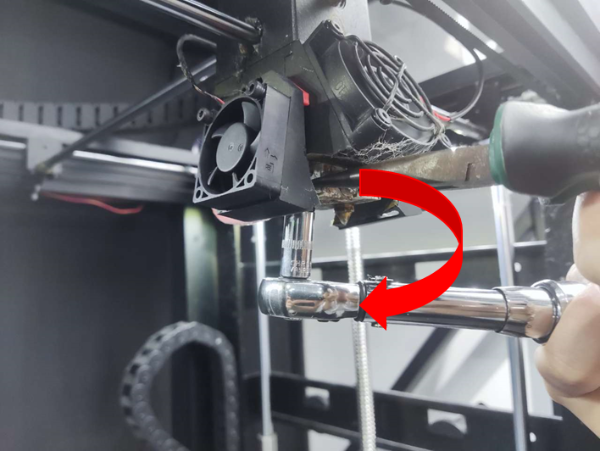
Figure 9 Loosen the nozzle with the sleeve.
5. Continue to turn the sleeve clockwise to remove the nozzle. Hold the removed nozzle carefully to avoid burns because it is very hot.
1. Prepare a new nozzle.

Figure 10 Prepare a new nozzle.
2. Select the left nozzle icon on the home page, set the left nozzle temperature to 180℃, and wait for the left nozzle temperature to rise to the specified temperature.

Figure 11 Heat the left nozzle.
3. When the temperature of the left nozzle rises to the specified temperature, turn off the power of the printer.
Note: Do not work on the printer with the power on to avoid personal injury and causing damage to the printer.

Figure 12 Turn off the printer power.
4. Use the sleeve to screw the nozzle into its original position on the heating block.
Note: At this point the temperature of the heating block is still very high, be careful of burns.
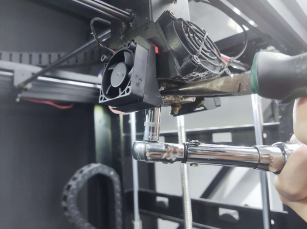
Figure 13 Install the new nozzle.
5. Hold the heating block with needle nose pliers to prevent the heating block from moving. Using a torque wrench (8mm socket), set it to 39±1kgf/cm (about 3.9N.m). Turn the torque wrench counterclockwise evenly at until the nozzle is tightened.
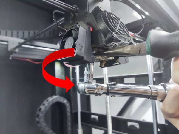
Figure 14 Firmly turn the sleeve to tighten the nozzle.
6.After installing the nozzle, shake the heating block slightly. If the heating block does not shake, it means that the nozzle are installed in place. If the heating block is shaking, there is a risk of filament leakage.
7. Ensure that there is a spacing of 0.1mm-0.6mm between the nozzle and the heating block after turning the nozzle.
1)A distance of 0.1mm must be reserved between the nozzle and the heating block.
Plug a 0.1mm feeler gauge between the nozzle and the heating block first, to test that the 0.1mm feeler gauge can be inserted into the gap. If the 0.1mm feeler gauge cannot be inserted into the gap, the nozzle is over-tightened. Please consult Raise3D after-sales support for assistance.
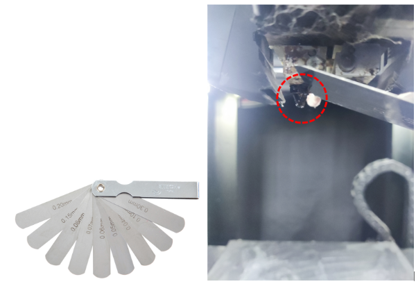
Figure 15 Check the spacing between the nozzle and the heater block with a feeler gauge.
2)A reasonable spacing between the nozzle and the heating block is 0.1mm-0.6mm. After you have confirmed that there is a 0.1mm space between the nozzle and the heating block, continue checking the spacing with a feeler gauge ≤0.6mm.
1. Calibrate the left nozzle.
1) On the "Home" interface , click the left nozzle and set its temperature to 180°C to check that the left nozzle can be heated normally.

Figure 16 Heat the nozzle.
2) In the "Utilities" interface, click the Z-axis home button to home the build plate.
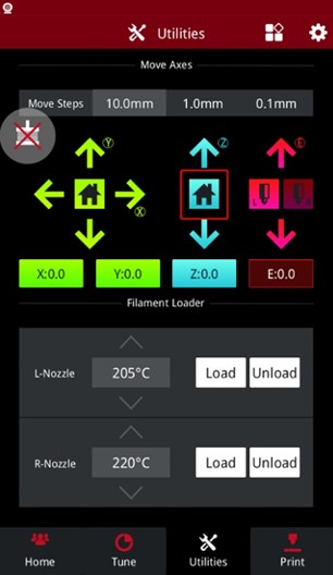
Figure 17 Home the build plate.
3) In the "Utilities" interface, Click the left nozzle icon , and click the down arrow to check whether the left nozzle can move normally.
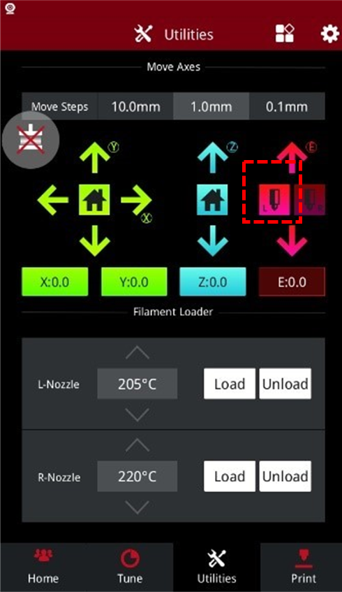
Figure 18 Check whether the left nozzle can move normally.
4) Click the left nozzle on the home page and set its temperature to 0℃, wait for the nozzle to come down to room temperature. Use the 0.3mm feeler gauge and place it under the left nozzle.
5) Rotate the larger thumbscrew in Figure 22 to lift the build plate and adjust the spacing between the nozzle and the build plate. Until the nozzle touches the sanded point on the feeler gauge, then you can feel the friction when you move the feeler gauge.
Note: Do not adjust the smaller screws on the side.
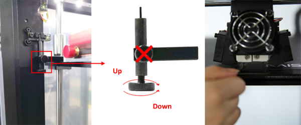
Figure 19 Adjust the left nozzle height.
6) In the "Utilities" interface, click the "Z Home" button to reset the Z axis. Then place the feeler gauge under the nozzle and re-adjust the thumbscrews to check the nozzle height again. The Z-axis should be homed after each fine-tuning screw. Repeat adjusting the screw until the desired nozzle height is achieved.
Note: Adjustments should be done gradually. The height change should not be very obvious after the Z axis is reset.
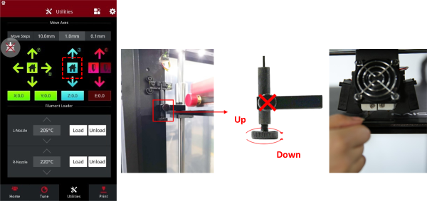
Figure 20 Re-adjust the left nozzle height.
4. Calibrate the right nozzle.
Note: Before calibrate the right nozzle, make sure that the left nozzle and the build plate are in the correct position.
1)In the "Home" interface, heat the right nozzle to 180°C to ensure that the right nozzle can be heated normally.
In the "Utilities" interface, click the right nozzle icon to activate the right nozzle, and then click the down arrow to ensure that the right nozzle can move normally.
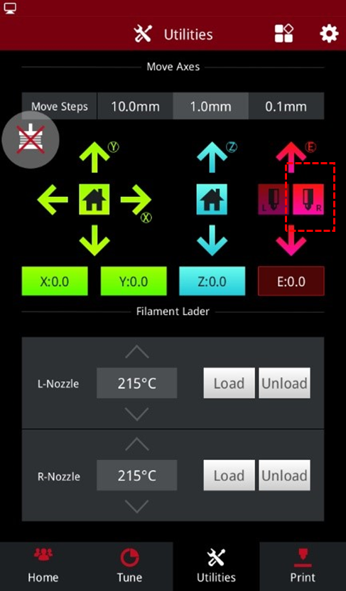
Figure 21 Activate the right nozzle.
2) In the "Home" interface, set the temperature of the right nozzle to 0°C. Wait for the right nozzle to come down to room temperature.
3) When the hot end has cooled down completely, place a 0.3mm feeler gauge under the right nozzle to check if the height is correct.
4) To adjust the height of the right nozzle, loosen the screw in the picture below and move the hot end by hand until the nozzle touches the feeler gauge.
Figure 22 Adjust the right nozzle height.
Note: Do not adjust the height of the build plate. Adjusting the build plate will affect the height of the left nozzle, if it has been adjusted, please re-calibrate the height of the left nozzle.
5) After adjusting the nozzle height, turn off the power of the printer and reinstall the fan.
Figure 23 Reinstall the fan.
-END-
