
Summary and Notes:
In this guide, we will cover replacement of the latest version of the Pro2 stepper motor driver. Additionally, we will cover replacing the new stepper motor driver cables that connect to the motion controller board (MCB) and the stepper motor.
Note: The instructions below will be specifically for the X axis driver and cables, however the process for the other two axis is similar.
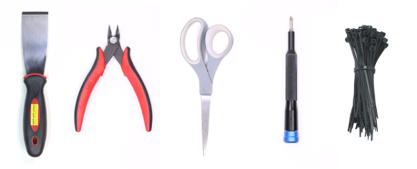
Tools
1) Phillips head screwdriver
2) Flush cutter/scissors
3) Spatula
4) Zip ties
Note: Some tools needed for this guide may not be included with the machine’s accessories.
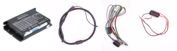
Components
1) Stepper motor driver
2) Pro2 stepper driver power cord V2
3) Pro2 stepper driver signal cord V2
4) Pro2 motor cable
Note: Images below are not to scale.
Let’s get started:
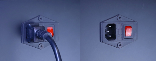
Step 1.) Power off and unplug the printer
It is very important that a printer is never energized when preforming repairs that will involve unplugging live connections.
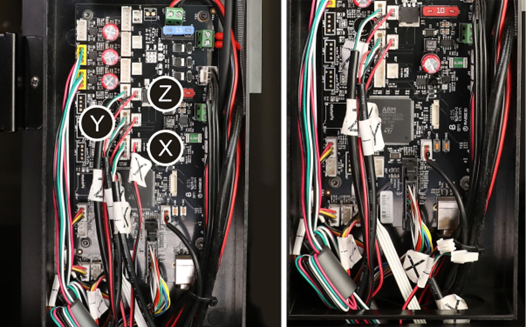
Step 2.) Access the motion controller board and unplug the driver connectors
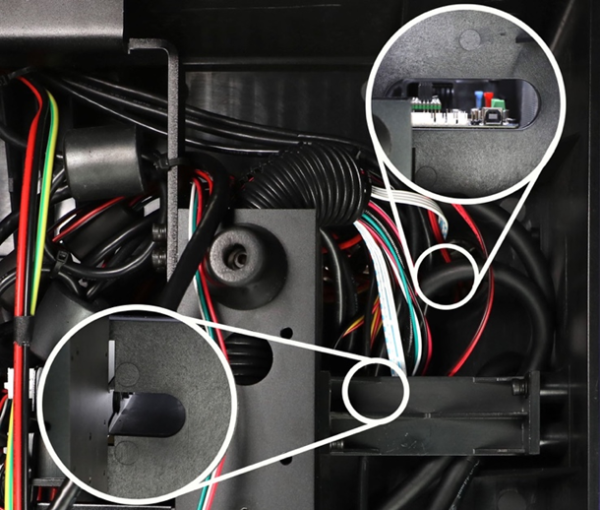
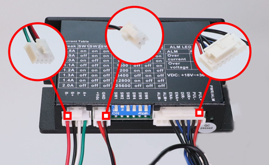
Open the filament compartment door and locate the small black panel with an electrical symbol on it. Using your spatula (or flat head screwdriver), gently pry the panel from the motion controller board compartment.

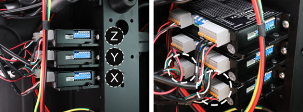
The stepper driver connections are located in the middle of the board. Each cable should be labeled with its designated axis. Unplug the X-axis four-pin connector as well as the smaller two-pin connector.
Note: There will be a few zip ties binding the cables together in the motion controller board compartment, these will need to be clipped and removed.
Step 3.) Remove the back panel
Using a Phillips head screwdriver, loosen and remove the ten screws securing the rear and side acrylic panel to the machine. (Plus models will have eleven screws)
Note: The back and side acrylic panels are attached together via a hinge. Upon loosening the screws, it is best practice to firmly push the panels towards the machine to ensure it does not fall when the screws are removed.
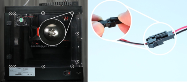
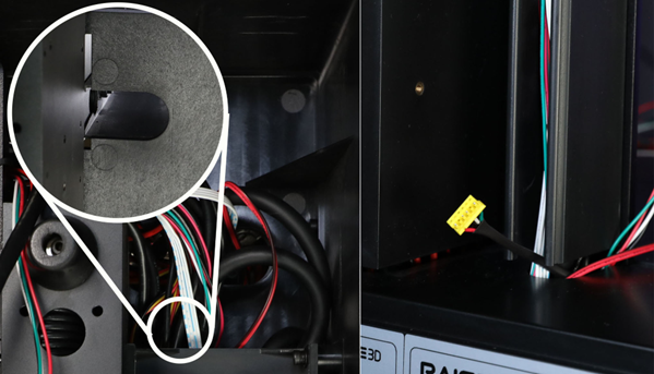
[!]When all the screws are removed the back and left side panel should be able to be removed, however the HEPA filter assembly is still attached. Most printers will have a small quick disconnect plug that you can use to quickly disconnect the filter fan from its cable.
[If you are working with an early batch Pro2 your machine may not include this quick connector. In this case the filter and fan would also need to be removed.]
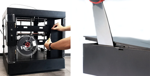
Step 5.) Unplug the stepper motor cable
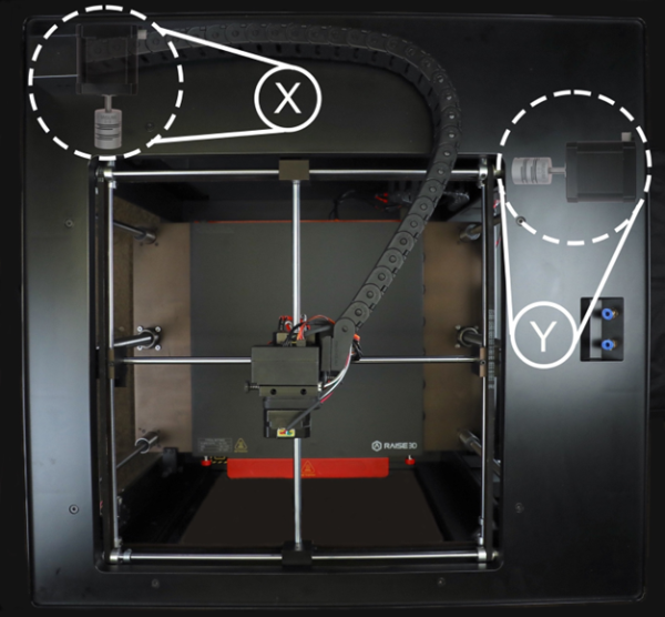
Now that the acrylic panel is removed you should have access to the motor underneath the top skirt of the machine. The X-axis stepper motor is located at the back left corner of the machine.
Note: If you are replacing the Z-axis driver and cables steps 6 & 7 can be skipped as the stepper motor is located on the bottom of the machine.
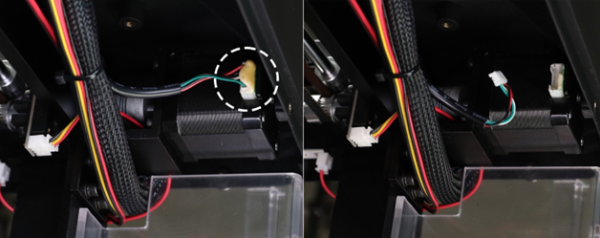
Grasping as close to the motor connector as possible, slightly wiggle and remove the stepper motor connector.
Note: From the factory the stepper motor connectors are secured in place with a small bead of glue. In order for the connector to be unplugged the glue will need to be removed first.
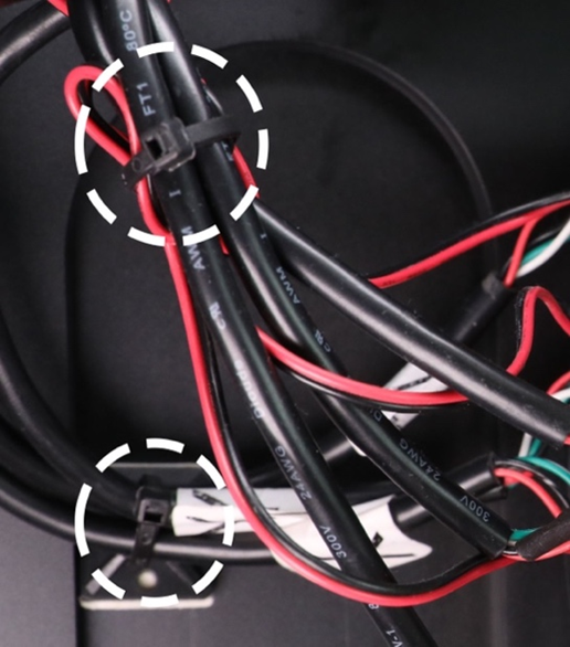
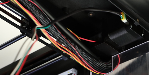
Once the connector has been unplugged, clip the following zip ties securing the motor cable to the top skirt.

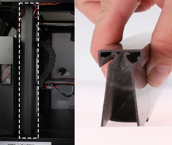
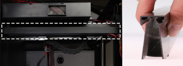
Step 7.) Remove the cable cover and begin to remove the stepper motor cable
The cable cover is press fit in place, to remove it pinch the two sides of the cable organizer and pull the cover off the organizer slot.
Once the cover has been pulled off, untangle the stepper motor cable from the rest of the cables in the organizer. This will allow the cable to be pulled out of the bottom of the printer with ease.
Step 8.) Turn the printer onto its left-hand side
[!]It is recommended to have two people, working together, when moving a machine to avoid injury or damage to the machine. Holding the top and bottom of the machine securely, gently tip the machine onto its left-hand side to expose the bottom panel.
Note: To ensure that machine does not get damaged, it is advised to lay a tarp or blanket down (on the side that you will be tipping the machine towards) if the floor or surface that the machine is located on is rough or littered with debris.
Step 9.) Remove the Phillips head screws securing the bottom panel
Using a Phillips head screwdriver, loosen and remove the four screws securing the bottom panel to the printer.
Note: If you are working on a newer model Pro2 there may be more screws holding on the bottom panel.
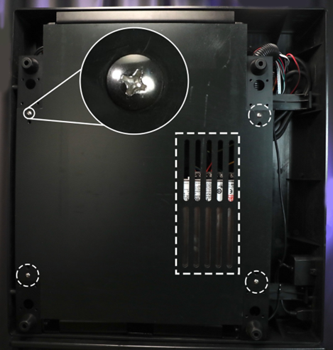
Step 10.) Locate and remove the stepper driver
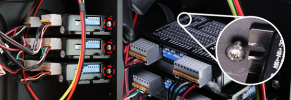
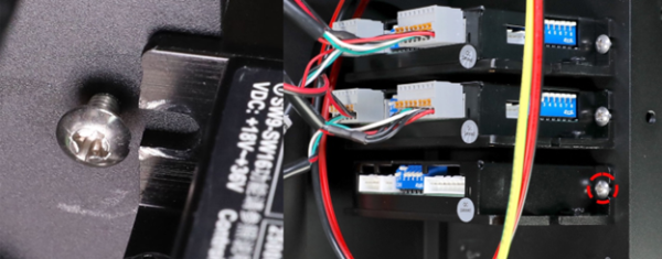
All printers come with the stepper drivers installed with the orientation that is annotated below. Once you have located the stepper driver that you will be replacing, unplug both grey connectors at the end of the driver.
Once the connectors have been removed loosen the Philips head screw securing the driver in place.
Note: Each driver is held in place by two Phillips head screws, however only one screw is accessible. (Annotated below) Once the screw is removed, you should be able pull the driver out of the frame. Slightly wiggling the driver up and down can help to loosen the non-accessible screw.
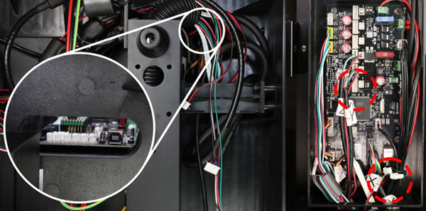
Step 11.) Cut the zip ties holding the driver cables in place
Using flush cutters or scissors clip all the zip ties that are securing the driver cables to the bottom of the printer.
[!]As there are numerous wires running in all different directions, please exercise caution when clipping the zip ties.
Note: Some cables may vary in length depending on if you are working with a standard or plus model.
Step 12.) Remove the old driver and motor cables
Gently start to pull the driver and motor cables out of the machine. While pulling the cables, take note of the two holes that the cables are coming out of. One side leads to the motion controller board compartment. The other side leads to the cable management slot running all the way to the top of the printer.
Note: The connectors may get caught on cables and corners while they are being pulled. Please be mindful to ensure that you do not damage any other connections.
Step 13.) Install the new V2 stepper motor driver
Now that the old driver has been removed, the non-accessible screw that was referenced in “Step 10” should be accessible. First slot the driver into the screw that is still in the frame. Once slotted, hold it in place while you secure the other screw with a Phillips head screwdriver.
Step 14.) Installing the new cables (Signal and Power cables)
Starting with the stepper driver power and signal cable, plug both cables into their respective slot on the driver. Thread the remaining ends up to the motion controller board compartment and plug the connectors into the board.
Next, using a Phillips head screwdriver, remove the grounding screw below the stepper drivers. With the screw removed, loop the grounding cable washer that is attached to the stepper driver signal cable, onto the grounding screw and re-install the screw to the side of the frame.
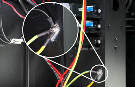
[!]Note: When routing the driver cables, please ensure that the connectors are routed to the proper location. The connectors on the cables are not universal. This means that only one end can plug into its respective driver slot.
Step 15.) Installing the new cables (Stepper motor cable)
Plug the stepper motor cable into its respective slot on the driver. Route the cable through the bottom of the printer and up into the cable management slot.
When the connector has been fished through the cable management slot, run the cable all the way up to the top of the printer and plug it into the X-axis motor.
Note: When routing the cable ensure that there is enough slack to run all the way across the top skirt of the printer an into the motor.
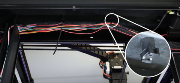
Next, secure the stepper motor cable to the top skirt along with the rest of the loose cables using zip ties.
Note: There will be small anchor points on the top skirt that the cables can be secured to.
Lastly, re-install the cable management slot cover.
Note: Before installing the cover ensure that all the cables are secured properly into the cable management slot.
Step 16.) Cable management
At this point the bottom of the printer can be quite frantic with multiple different cables going in all different directions. Using zip ties and the anchor points at the bottom of the machine cable manage all the excess cables and secure them to the machine’s undercarriage.
Note: There is no right or wrong way to manage and secure the cables. The main things to keep in mind is that there is no undo stress put on any of the connections and that there is no excess slack that could droop from the bottom of the machine.
[!]As there are numerous wires running in all different directions, please ensure to exercise caution when clipping the cable ties.

Step 17.) Re-install the bottom panel
Using a Phillips head screwdriver re-install the bottom panel.
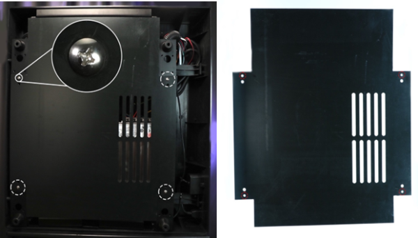
Note: Ensure that vent orientation is sitting above the power supply so that airflow can reach the PSU.
Step 18.) Turn the printer back upright
[!]It is recommended to have two people, working together, when moving a machine to avoid injury or damage to the machine. Holding the top and bottom of the machine securely, gently tip the machine back to its upright position.
Step 19.) Re-install the back panel
Start off by holding the panels close enough to the machine so that the HEPA filter fan can be re-connected. When the fan is connected tilt the panel forward so that the HEPA filter assembly can be tucked underneath the top skirt and panels can sit flush with the top and bottom skirt.
Once the panels are flush, use a Phillips head screwdriver to re-install all 10 screws into these locations.

Step 20.) Re-install the motion controller board compartment cover
Using a spatula or flat head screwdriver gently bend the compartment wall so that the motion controller board cover can be re-installed.
[13.039-EN.2.0.20230829-Pro2 Series-How to Replace the Stepper Motor Driver]
-END-
