
[ Manual Pro2 Series - 034 Nozzle Height Calibration-V1.0 ]
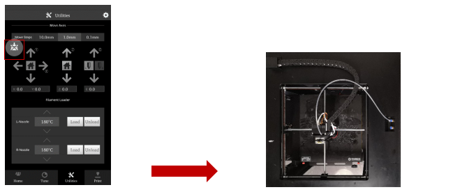
1. Home the build plate, and set the movement increment to 10mm. This will be located in the “Move Steps” bar on the top of the screen. Press the down arrow 25 times to drop the build plate’s height to 100mm.
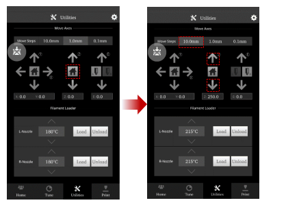
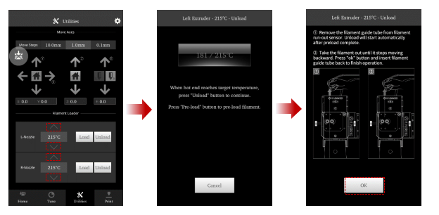
2. Set both extruders to the proper unloading temperature. The recommend target temperature is typically 5-10C higher than its common printing temperature. Press ‘Unload’ to begin the unloading process. After the unloading process has completed, remove the filament and filament guide tube from the extruder.
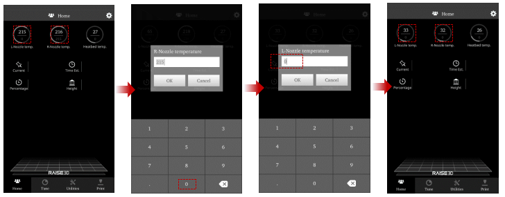
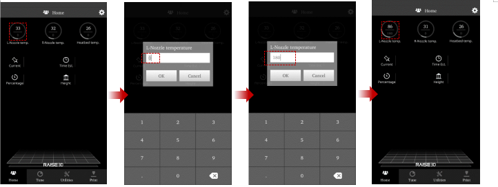
3. Open the ‘Home’ tab, and click on the nozzle temperature. In the new window, set the temperatures for both nozzles to 0, and press OK. Allow the components to cool down completely before continuing.
When the extruders reach an ambient temperature, power off the printer.
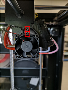
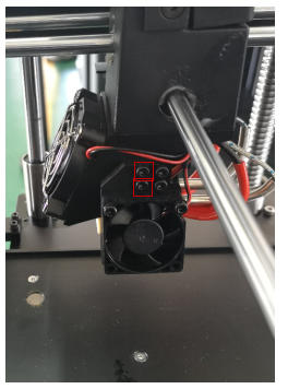
4. Remove the screws from the cooling fan with a 2.5mm hex wrench.
5. Push the hot end all the way up until the heat sink touches the collet.
Secure this position by tightening the clamping screw depicted in the photo below.
6. Remove the screws from the right side cooling fan.
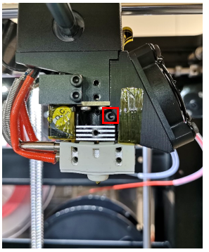
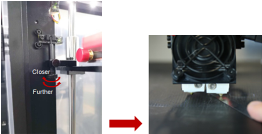
7. Loosen the screw marked in red with 2.5mm hex wrench.

8. Push the hot end all the way up until the heat sink touches the collet.
Secure this position by tightening the clamping screw.
9. Raise the Z limit pin by rotating the bottom screw 1 turn counter clockwise from a top down perspective
10. Home Z
11. Disable the motor with the ‘Disable Motor’ button located in the top left of the screen. This will allow you to freely reposition the extruder by hand.
Move the extruder head along the rods into the center position.
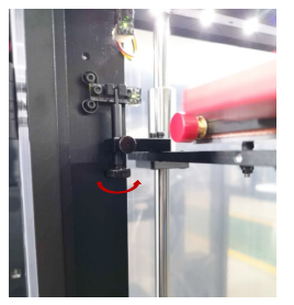
12. Use the feeler gauge (included in the printer toolkit) and place it underneath the left nozzle. When properly calibrated the feeler gauge should have friction between the bed and nozzle without requiring excessive force.
To adjust the nozzle height, rotate the large thumbscrew as depicted in the diagram.
DO NOT adjust the smaller side-mounted screw.
**Adjustments should be made incrementally. Changes in height will not be visible until after homing.
Home the Z-Axis, then verify the new height using the feeler gauge.
Homing is required each time the knob is adjusted. Repeat until desired result is achieved.

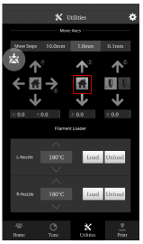
13. From the home screen, heat the right nozzle to 180. Enable the right nozzle by pressing the icon,then the down arrow. Once the nozzle is enabled, set the temperatures to 0, and allow them to cool completely before continuing.

14. Once the hotend has cooled completely, Insert the feeler gauge under the right nozzle and check for proper height. If the nozzle needs further adjustments, loosen the setting screw, and manually move the hotend until it is able to come in contact with the feeler gauge.
**DO NOT adjust the bed height. Adjusting the bed will affect the left nozzle, which will require recalibration starting from step 9.
15.Tighten the screw into this position.
[ Manual Pro2 Series - 034 Nozzle Height Calibration-V1.0 ]
-END-
