
[ Manual Pro2 Series - 013 Nozzle Offset Calibration-V1.0 ]
Ensure Nozzle heights are calibrated properly before calibrating offsets.
Open ideaMaker. Click “File” and select “Examples”.
Select“Cablibration-Extruder-Offset.idea”.

1. Print Calibration Model 1
Locate the USB storage drive that was included within the accessory box of your Pro2 Series packaging. Connect this drive to an available USB port on the side of the touchscreen.
Ensure PLA is loaded in both extruders then.
From the ‘Print’ tab, locate the pre-sliced files include in the flash drive. Select “Dual Head Calibration 1. Gcode” model, and press Print.
If you do not have Your flashdrive with this file or would like to use materials other than PLA you can find the model in ideamaker under file>examples>Calibration-Extruder-Offset.idea.
We recommend printing with a wipe wall or wipe tower for best results.
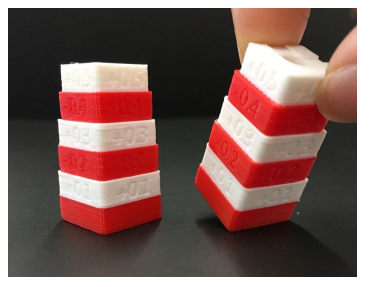
2. View the printed model from the top surface and align this to the visual graphic seen on screen. The direction can be identified with the large notch along the Y direction, and the small notch in the X direction.
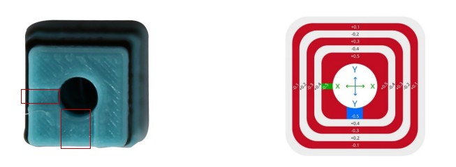
3.Measure Offset
This is position is X Offset = 0, Y Offset = 0.
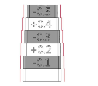

In the case above, the values are: X Offset = + 0.2mm, Y Offset = -0.3mm.
Calculate the offset using the formula on the next page.
4.Adjust the Offset
Using the touchscreen on the printer, adjust the extruder offsets by navigating to the extruder settings. This can be found under Setting > Machine > More Settings > Hardware > Extruders.

Check they X and Y offsets and add your recorded values to what is shown on the screen. If X was set to 25 and Y was set to 0 we would end with the values shown above based on the example from step 3.
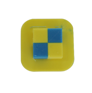
5.Print Calibration Model 2
Ensure PLA is loaded on both sides.
Use the same USB drive as depicted in step 1. Open the ‘Print’ menu and select the “Dual Head Calibration 2.Gcode”. Press Print.
The model should resemble the model below.
This model can also be found under file>examples>Dual-Color-Cube.idea. if you do not have the flashdrive with the file or would like to use material other than PLA.
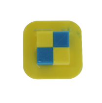
6. Check for obvious gaps between the colored blocks. (refer to diagram below)
[ Manual Pro2 Series - 013 Nozzle Offset Calibration-V1.0 ]
-END-
