
* Please review this entire manual before operating the printer.
WARNING
This is a class A product. In a domestic environment, this product may cause radio interference, in which case the user may be required to take adequate measures.
Liability Statement
The information in this manual is subject to change without notice. Shanghai Fusion Tech Co. Ltd. (also referred to as "Raise3D" here) is not responsible for errors in this manual. Raise3D does not take any responsibility for incidental or secondary losses caused by the supply, performance or use of this manual. Raise3D does not make any guarantees for this manual, including but not limited to implied guarantees for marketability and suitability for specific purposes. The system owner/material purchaser is responsible for determining whether the Raise3D material is safe, legal, and technically suitable for the intended application, and at the same time determining the appropriate disposal (or recycling) method in compliance with local environmental regulations. Unless Raise3D's standard sales conditions are stipulated, Raise3D will not be liable for any losses caused by the use of the products described in this manual. The system owner/material purchaser is responsible for determining whether the materials used meet the requirements of Raise3D, otherwise Raise3D will not be responsible for any losses caused by the use of the products described in this manual.
Copyright Statement
This document is protected by copyright and all rights are reserved. The use, disclosure and possession of this document are restricted by the software copyright and the agreement established by Raise3D. Nothing in this document may be photocopied, reproduced, or translated into another language, unless prior written permission from Shanghai Fusion Tech Co. Ltd. is obtained.
All drawings and information in this manual are the property of Shanghai Fusion Tech Co. Ltd. All unauthorized use and copying are prohibited.
Trademark Property Statement
Raise3D and ideaMaker are registered trademarks of Shanghai Fusion Tech Co. Ltd.
WINDOWS is registered trademark of Microsoft Corporation.
macOS is a registered trademark of Apple Inc.
All other product names and trademarks are the property of their respective owners, and Raise3D is not responsible for the selection, performance or use of these non-Raise3D products. Product specifications are subject to change without notice.
Please read the safety information to ensure that you use the appliance safely.
General Information
You can find general information about this instruction manual here.
§ Read this instruction manual carefully. Only this will ensure you use the appliance safely and efficiently.
§ This manual is intended for the installer and the user of the appliance.
§ Follow the safety instructions and warnings.
§ Keep the instruction manual and the product information safe for future reference or for the next owner.
§ Check the appliance after unpacking it. Do not connect the appliance if it has been damaged in transit.
§ If you have any questions, please contact our local service center or distributors.
§ Any failure and losses caused by ignoring the following mentioned items, and cautions mentioned in the operation and installation instruction are not covered by our warranty and any liability.
Intended Use
Read the information on intended use to ensure that you use the appliance correctly and safely.
Only use this appliance:
§ According to this installation and instruction manual;
§ In a well-ventilated and dry environment;
§ The environmental conditions used are:
Operating Ambient Temperature: 15-30°C, 10-90% RH non-condensing
Storage Temperature: -25°C to +55°C, 10-90% RH non-condensing
Restriction on User Group
§ Keep children, pets and vulnerable persons away from the appliance.
§ This equipment is not suitable for use in locations where children are likely to be present.
§ This equipment is only allowed to be used by skilled person. This appliance may be used by people who have reduced physical, sensory or mental abilities or inadequate experience and/or knowledge, provided that they are supervised or have been instructed on how to use the appliance safely and have understood the resulting dangers.
Safe Installation
Take note of the safety instructions when installing the appliance.
WARNING - Risk of electric shock!
§ Improper installation is dangerous.
Connect and operate the appliance only in accordance with the specifications on the rating plate.
Connect the appliance to a power supply with alternating current only via a properly installed socket with earthing.
The protective conductor system of the domestic electrical installation must be properly installed. The installation must have a sufficiently large cross section.
Please ensure that the power supply system (current, voltage and cables) can meet the normal load requirements of the electrical appliances.
Never equip the appliance with an external switching device, e.g. a timer or remote control.
When installing the appliance, check that the power cable is not trapped or damaged.
Select the fuse according to the fuse safety identification requirements.
The power plug and the socket must match and the grounding blade must work properly, and the body must be properly grounded.

§ If the insulation of the power cord is damaged, this is dangerous.
Never let the power cord come into contact with hot appliance parts or heat sources.
Never let the power cord come into contact with sharp points or edges.
Never kink, crush or modify the power cord.
§ When the machine is plugged in, touch the machine shell and find that there is electrostatic inductance. This indicates that the machine in the home is not well grounded. Please unplug the machine and repair the power connection immediately to ensure a good grounding.
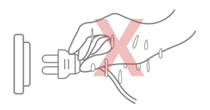
§ Do not connect the power supply with wet hands.
§ If you have any questions, please consult a professional electrician.
WARNING - Risk of fire!
§ It is dangerous to use an extended power cord and non-approved adapters.
Do not use extension cables or multiple socket strips.
If the power cord is too short, contact Customer Service.
Only use adapters approved by the manufacturer.
§ If the insulation of the power cord is damaged, it is very dangerous.
WARNING - Risk of injury!
§ The high weight of the appliance may result in injury when lifted.
Do not lift the appliance on your own.
WARNING - Risk of suffocation!
§ Children may put packaging material over their heads or wrap themselves up in it and suffocate.
Keep packaging material away from children.
Do not let children play with packaging material.
WARNING - Risk of injury!
§ The appliance may vibrate when in use.
Place the appliance on a clean, even, solid surface.
§ If tubes and power cords have been laid incorrectly, this can cause a tripping hazard.
Lay tubes and power cords in such a way that there is no risk of tripping.
§ If the appliance is moved by holding onto protruding components, such as the appliance door, the parts may break off.
Do not move the device by holding onto protruding parts.
WARNING - Risk of cutting!
§ Touching sharp edges on the appliance may lead to cuts.
Do not touch the sharp edges on the appliance.
Wear protective gloves when installing and transporting the appliance.
Safe Use
Follow these safety instructions when using the appliance.
WARNING - Risk of electric shock!
§ If the appliance or the power cord is damaged, this is dangerous.
Never operate a damaged appliance.
Never pull on the power cord to unplug the appliance. Always unplug the appliance at the mains.
If the appliance or the power cord is damaged, immediately unplug the power cord.
Call Customer Service, please refer to the Chapter of Experiencing Difficulties/Contact Information.
Repairs to the appliance should only be carried out by trained specialist staff.
§ An ingress of moisture can cause an electric shock.
Never expose the appliance to intense heat or humidity.
Do not use steam cleaners or sprays to clean the appliance.
WARNING - Risk of harm to health!
§ Children can lock themselves in the appliance, thereby putting their lives at risk.
Do not install the appliance behind a door as this may obstruct the appliance door or prevent it from opening.
With redundant appliances, unplug the power cord and cut through the cord.
WARNING - Risk of suffocation!
§ Children may breathe in or swallow small parts, causing them to suffocate.
Keep small parts away from children.
Do not let children play with small parts.
CAUTION - Risk of injury!
§ The covering plate may break if you stand on or climb onto the appliance.
Do not stand on or climb onto the appliance.
§The appliance may tip over if you sit on or lean against the open door.
Do not sit on or lean against the appliance door.
Do not place any objects on the appliance door.
§ Reaching into the chamber while the three-axis system is still moving may cause hand injuries.
Wait for the three-axis system to come to a complete stop before reaching inside.
§ The spatula provided in the accessory box has sharp parts. If the spatula is used improperly, the user may be injured.
Do not touch the edge of the spatula.
Keep children away from the spatula.
§ Some parts in the printer are sharp and may cause injury.
§ When removing the printing model, please refer to the Chapter of Remove the Printed Model.
CAUTION - Risk of burns!
§ When operating or printing at high temperatures, the shell of the appliance becomes hot.
Do not touch the build plate when the printer is heating up.
Please wear the heat-insulating gloves provided in the accessory box for operation.
Please keep children away from the heated build plate.
§ The temperature of the extruder is very high when it is printing.
Please do not touch the extruder when it is heating.
Please wear the heat-insulating gloves provided in the accessory box for operation.
Please keep children away from the heated extruder.
Safe Maintenance
Take note of the safety instructions when performing maintenance work on the appliance.
WARNING - Risk of electric shock!
§ Improper repairs are dangerous.
Repairs to the appliance should only be carried out by trained specialist staff.
Only use the manufacturer's original spare parts and original accessories when repairing the appliance.
If the power cord of this appliance is damaged, it must be replaced by the manufacturer, the manufacturer's Customer Service or a similarly qualified person in order to prevent any risk.
§ An ingress of moisture can cause an electric shock.
Do not use steam cleaners or sprays to clean the appliance.
WARNING - Risk of injury!
§ The use of non-original spare parts and non-original accessories is dangerous.
Only use the manufacturer's original spare parts and original accessories.
Hot Surface: The hot surface sign indicates the presence of devices with high temperatures. Always be extremely careful when working around heated components.
Wait half an hour after switching off the printer before handling parts to prevent burns.

Moving Parts: Do not put fingers, clothing or hair into gears and other hazardous parts to avoid electric shock, injury, fire, or damage to the device.

High Voltage: The high voltage sign indicates the presence of high voltages. Always stay away from exposed circuitry. It is recommended that all conductors be removed.

Replacement Fuse Identification and Rating Markings: Identification of a suitable replacement fuse shall be marked adjacent to the fuse holder.

Protective Earthing Conductor Terminal: Marked near the protective earthing conductor terminal.

FCC Statement
Please take attention that changes or modification not expressly approved by the party responsible for compliance could void the user’s authority to operate the equipment.
This device complies with Part 15 of the FCC Rules. Operation is subject to the following two conditions:
(1) This device may not cause harmful interference, and
(2) This device must accept any interference received, including interference that may cause undesired operation.
This equipment complies with FCC radiation exposure limits set forth for an uncontrolled environment. This equipment should be installed and operated with minimum distance 20cm between the radiator & your body.
EU Conformity Statement
| This product and-if applicable-the supplied accessories too are marked with “CE” and comply therefore with the applicable harmonized European standards listed under the RE Directive 2014/53/EU, the EMC Directive 2014/30/EU, LVD Directive 2014/35/EU, the RoHS Directive 2011/65/EU. |
| 2012/19/EU (WEEE directive): Products marked with this symbol cannot be disposed of as unsorted municipal waste in the European Union. For proper recycling, return this product to your local supplier upon the purchase of equivalent new equipment, or dispose of it at designated collection points. For more information see: http:// www.recyclethis.info. |
| 2006/66/EC (battery directive): This product contains a battery that cannot be disposed of as unsorted municipal waste in the European Union. See the product documentation for specific battery information. The battery is marked with this symbol, which may include lettering to indicate cadmium (Cd), lead (Pb), or mercury (Hg). For proper recycling, return the battery to your supplier or to a designated collection point. For more information see: www.recyclethis.info. |
UKCA Conformity Statement
| This product is marked with "UKCA" and in conformity with the relevant UK statutory requirement: Radio Equipment Regulations 2017. Full text of the UK declaration of conformity is available at https://www.raise3d.com. |
UK sales partner company name:3DGBIRE Ltd UK sales partner company address: 3DGBIRE, Unit 44/45 Chorley North Industrial Estate, Drumhead Road, Chorley, Lancashire, PR67BX | |
Electromagnetic Compatibility - EMC
Simplified EU Declaration of Conformity
Raise3D declares that this device is in compliance with the essential requirements and
other relevant provisions of Directive 2014/53/EU. Full text of the EU declaration of
conformity is available at https://www.raise3d.com.
RF Exposure Information
This device has been tested and meets applicable limits for Radio Frequency (RF) exposure.
This equipment must be installed and operated in accordance with provided instructions and the antenna(s) used for this transmitter must be installed to provide a clearance of at least 20 cm from all persons and must be co-located or operating in conjunction with any other antenna or transmitter.
CE&UKCA Mark Warning
The device is restricted to indoor use only when operating in the 5150 to 5250 MHz frequency range.
|
|
| |||||
| BE | EE | HR | IT | CY | LV | LT |
BG | IE | LU | HU | MT | NL | AT | |
CZ | EL | PL | PT | RO | SI | SK | |
DK | ES | FI | SE | DE | FR | LI | |
NO | IS | CH | TR | UK(NI) | UK |
| |
CE&UKCA Output Power Table:
Function | Frequency | Frequency |
Wi-Fi | 2412-2472 MHz | 18 dBm(b)/ 18 dBm(g)/ 13dBm(HT) |
5150-5250 MHz | 19 dBm(a)/ 18.5 dBm(HT20)/ 17.5 dBm(HT40) | |
5725-5850 MHz | 14 dBm(a)/ 14 dBm(HT20)/ 14 dBm(HT40) |
FCC Output Power Table:
Function | Frequency | Frequency |
Wi-Fi | 2412-2462 MHz | 18.31 dBm(b)/ 15.62 dBm(g)/ 14.9dBm(HT) |
5150-5250 MHz | 15.36 dBm(a)/ 14.79 dBm(HT20)/ 14.41 dBm(HT40) | |
5725-5850 MHz | 15.48 dBm(a)/ 14.49 dBm(HT20)/ 14.06dBm(HT40) |
Installation
To facilitate operation and maintenance, maintain a proper distance of 50 cm on the side of the printer, 80 cm on the front, 20 cm on the back, and 60 cm on the top during installation. No flammable materials are allowed around the installation location.
Note: During low-temperature transportation, the printer may encounter frost or icing hazards. The printer can be stored at room temperature for 4-6 hours before operating.
Filament and Electrical Precautions
It is strongly recommended to use Raise3D official filaments and/or default settings for better performance. The Raise3D printer is designed to be highly compatible with Raise3D official filaments. Be extremely careful when printing with unverified filaments and settings to prevent abnormal printing results or damaging the printer.
Warning: The printer belongs to EN55032 Class A. In a residential environment, the printer may cause radio interference.
Odor
The printer emits a thermoplastic smell when in operation.
Note: Place the printer in a well-ventilated and dry environment.
Oil in the air accumulating inside the printer may damage plastic parts. Air in a cavity with excessive solid particles (conductive or non-conductive) may cause damage to the printer.
Printer | Raise3D Pro3 HS | Raise3D Pro3 Plus HS | |||
Build Volume (W×D×H) | Single Extruder Print | Dual Extruder Print | Single Extruder Print | Dual Extruder Print | |
300×300×300 mm (11.8 × 11.8 × 11.8 inch) | 255×300×300 mm (10 × 11.8 × 11.8 inch) | 300×300×605 mm (11.8 × 11.8 × 23.8 inch) | 255×300×605 mm (10 × 11.8 × 23.8 inch) | ||
Machine Size (W×D×H) | 620×626×760 mm (24.4 × 24.6 × 29.9 inch) | 620×626×1105 mm (24.4 × 24.6 × 43.5 inch) | |||
Weight | Net Weight | Gross Weight (Carton with Pallet) | Net Weight | Gross Weight (Carton with Pallet) | |
54 kg (119 lbs) | 75.7 kg (166.9 lbs) | 64 kg (141 lbs) | 88.7 kg (195.5 lbs) | ||
General | Print Technology | Fused Filament Fabrication (FFF) | |||
Print Head System | Dual-head with Electronic Lifting System | ||||
Filament Diameter | 1.75 mm | ||||
XYZ Step Size | 0.78125, 0.78125, 0.078125 micron | ||||
Standard Printing Speed | 300 mm/s | ||||
Build Plate | Flexible Steel Plate with BuildTak | ||||
Build Plate Leveling | Mesh-leveling with Flatness Detection | ||||
Heated Bed Material | Silicone | ||||
Heated Bed Max Temperature | 120°C | ||||
Nozzle Diameter | 0.4 mm (Default), 0.2/ 0.6/ 0.8/ 1.0 mm (Available) | ||||
Max Nozzle Temperature | 320°C | ||||
Layer Height | The Pro3 HS Series is compatible with 0.2, 0.4, 0.6, 0.8 and 1.0 mm nozzles, and the layer height can vary between 0.05-0.6 mm. To achieve stable print results, when using 0.4 mm nozzles, we recommend using a layer height between 0.1-0.3 mm. | ||||
Automatic Filament Switching | Available (Coming Soon) | ||||
RFID Sensor | Available (Coming Soon) | ||||
Filament Run-Out Sensor | Available | ||||
Filter | HEPA Filter with Activated Charcoal | ||||
EVE Smart Assistant | Available | ||||
Connectivity | Wi-Fi, LAN, USB port, Live Camera | ||||
Noise Emission | < 55 dB (A) When Building | ||||
Operating Ambient | 15-30°C, 10-90% RH, non-condensing | ||||
Storage Temperature | -25°C to +55°C, 10-90% RH, non-condensing | ||||
Electrical | Power Supply Input | 100-240 VAC, 50/60 Hz 230 V @ 3.3 A | |||
Power Supply Output | 24 V DC, 600 W | ||||
Material | Material Type | Hyper Core: PPA CF/ PPA GF/ ABS CF Hyper Speed: PLA/ ABS Industrial: PPA CF/ PPA GF/ PET CF/ PET GF/ PETG ESD/ PET Support/ PPA Support Premium: PLA/ ABS/ ASA/ PETG/ PC/ TPU-95A/ PVA+ | |||
Third Party Material | Supported by Raise3D OFP (Open Filament Program)* | ||||
Software | Slicing Software | ideaMaker | |||
Supported File Types | STL/ OBJ/ 3MF/ OLTP/ STEP/ STP/ IGES/ IGS | ||||
Supported OS | Windows/ macOS/ Linux | ||||
Machine Code Type | GCODE | ||||
Printer Controller | User Interface | 7-inch Touch Screen | |||
Network | Wi-Fi, Ethernet | ||||
Power Loss Recovery | Available | ||||
Screen Resolution | 1024×600 | ||||
Motion Controller | Atmel ARM Cortex-M4 120MHz FPU | ||||
Logic Controller | NXP ARM Cortex-A9 Quad 1GHz | ||||
Memory | 1 GB | ||||
Onboard Flash | 16 GB | ||||
OS | Embedded Linux | ||||
Ports | USB 2.0×2, Ethernet×1 | ||||
*For detailed information and slicing profiles of the materials supported by Raise3D OFP, please visit https://www.ideamaker.io/.
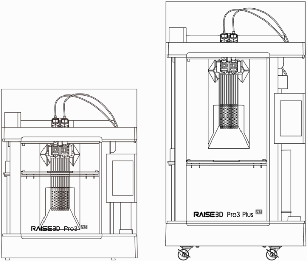
Pro3 HS
Pro3 Plus HS
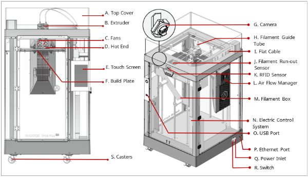
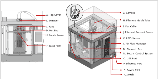
A. Top Cover
The upper cover of the printer.
B. Extruder
The part extruding filament to the hot end. Brand-new unitized extruders, which are more convenient for assembly and dismounting. The printer’s dual extrusion structure can adapt to a variety of filaments.
C. Fans
The part used to cool the heat down.
D. Hot End
The part that melts filaments. With a quick-release design, even beginners can quickly remove the hot end within one minute, making it more convenient to repair the hot end after removing it.
E. Touch Screen
The part that you can control the printer and check the printer status.
F. Build Plate
A plate for printing the model.
G. Camera
The part used to observe the operation of the printer.
H. Filament Guide Tube
The part that protects and guides filaments.
I. Flat Cable
The integrated cable that transmits the signal from the motion controller board to the extruder. The latest flat cable iteration reduces drag on the printhead and avoids the sagging of the cross shaft.
J. Filament Run-out Sensor
An automated optical detection system is adopted to detect whether the filaments are sufficient. When the filaments are running out, the printer will automatically stop printing.
K. RFID Sensor
Uses RFID tags and readers for information transmission and identification between the printer and filaments.
L. Air Flow Manager
An air filter manager including a fan and a HEPA filter, which is used to enhance air circulation inside the printer.
M. Filament Box
The place where the filament is discharged, which can accommodate 2 spools of 1kg filaments at the same time.
N. Electric Control System
It stores the motion controller board.
O. USB Interface
Two USB2.0 interfaces.
P. Ethernet Port
RJ45 is connected to the port to connect your printer to a network.
Note: The length of the network cable should not exceed 3 m.
Q. Power Inlet
The place to connect power cable.
R. Switch
The power switch to turn on/off the printer.
S. Casters
Four swiveling and double-locking casters.
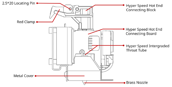
Hyper Speed Hot End
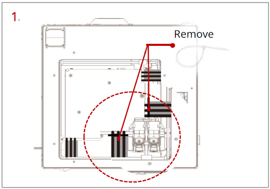
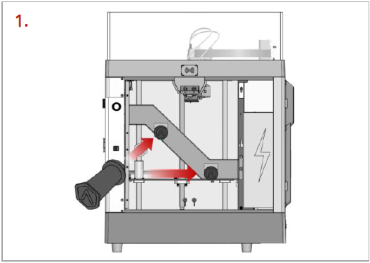
Remove, but do not cut, the four shipping zip ties for fixing the Z axes. Keep the shipping zip ties safe for further installation and subsequent transportation.
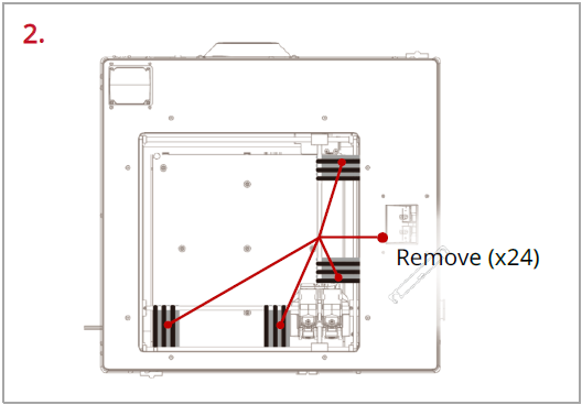
Before powering on the printer, make sure to peel off all the yellow stickers and remove the 24 security spacers. If the spacers are not removed, the spacers will damage the printer once the printer begins operating. Keep the security spacers carefully for further installation and subsequent transportation.
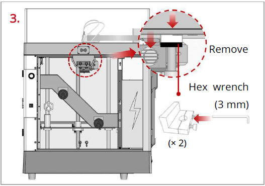
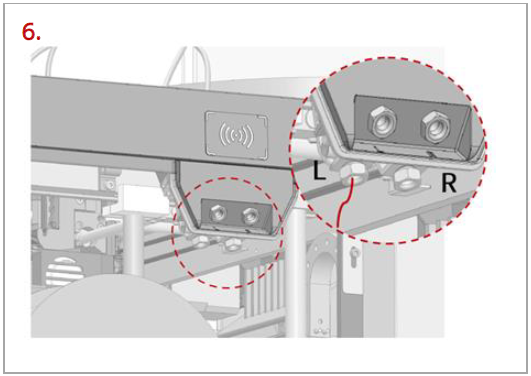
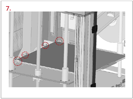
Remove the 4 screws on the screw clamps, using the included 3 mm hex wrench. The clamps are located on the top of the screw rods on the left and right sides of the printer. Keep the screw clamps and screws safe for further installation and subsequent transportation.
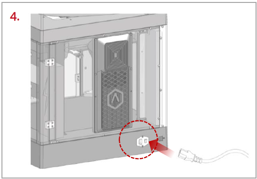
The printer contains a power cord that conforms to your current country (region). Connect it to the power inlet and outlet. Flip the switch of the printer.
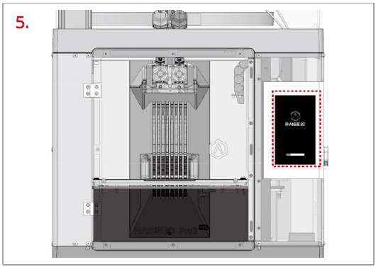
After the printer is powered on, the printer will enter the boot process. It takes about 60 seconds for the printer to enter the Start-up Wizard.
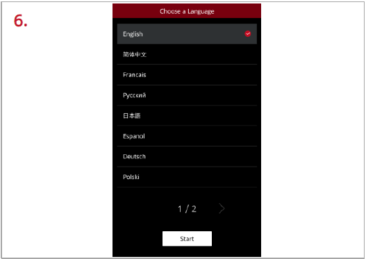
After the printer has entered the Start-up Wizard, you can follow the prompts on the screen for further operations, such as choosing the language for the printer.
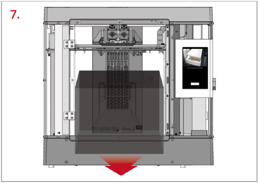
After confirming that all the safety spacers and screws are removed according to the screen prompts, tap “Next”. Open the front door, and take out the accessory box and filament box from the printer.
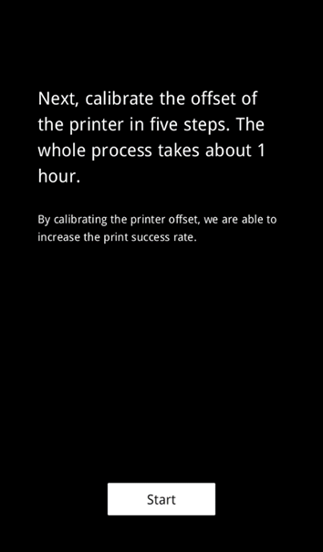
8. Keep following the Start-up Wizard to complete the basic settings, such as printer’s name, network, and RaiseCloud. After completing the basic settings, the printer will carry out the offset calibration (See chapter E for details).
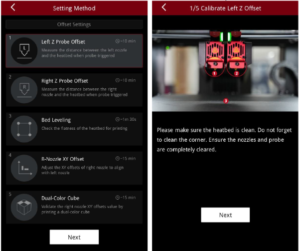
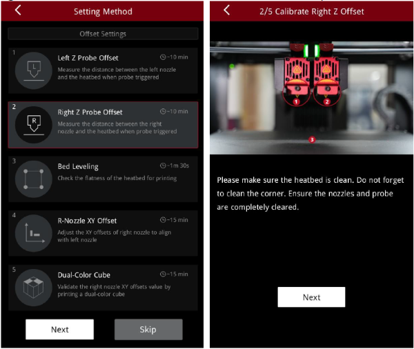
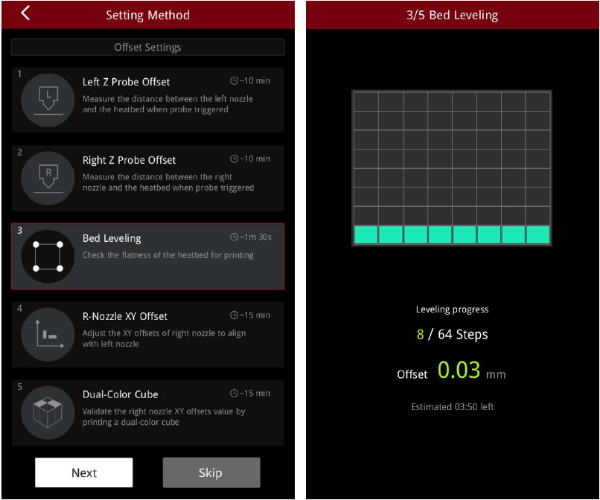
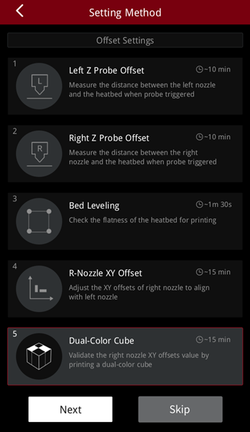
1. Offset calibration is to ensure that your printer will print successfully. There are 5 steps in the whole offset value calibration in the Start-up Wizard, and the whole process takes about 1 hour.
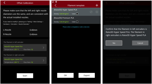
2. Please select an appropriate filament template, such as Raise3D Hyper Speed PLA, or you can add a new filament template. Raise3D Hyper Speed PLA filament is used for the calibration process in this tutorial.
Note:
1) It is recommended to use the same type of filaments for Offset Calibration. It is also recommended to use Raise3D Hyper Speed filaments.
2) When running the "R-Nozzle XY Offset" and "Dual Color Cube" in the Offset Calibration, PLA filaments must be used.
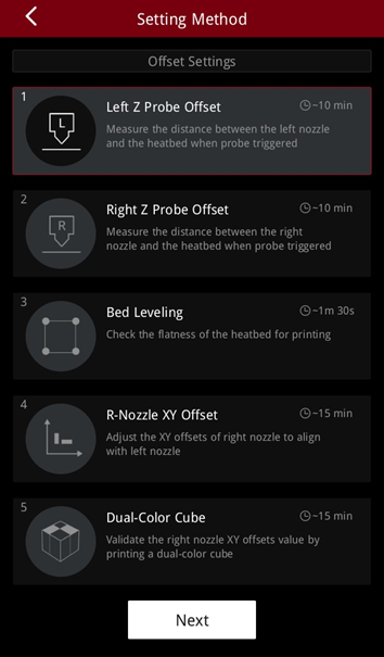
3. Run the 5-step Offset Calibration sequentially according to the prompts on the screen.
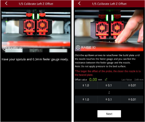
1. Enter the Left Z Probe Offset. Make sure that the nozzle and build plate are clean.
2. With a 0.3 mm feeler gauge, adjust the distance between the nozzle and the build plate as indicated by the prompts on the screen. Make sure that you can feel some resistance as the feeler gauge moves between the nozzle and build plate. Do not press hard on the build plate.
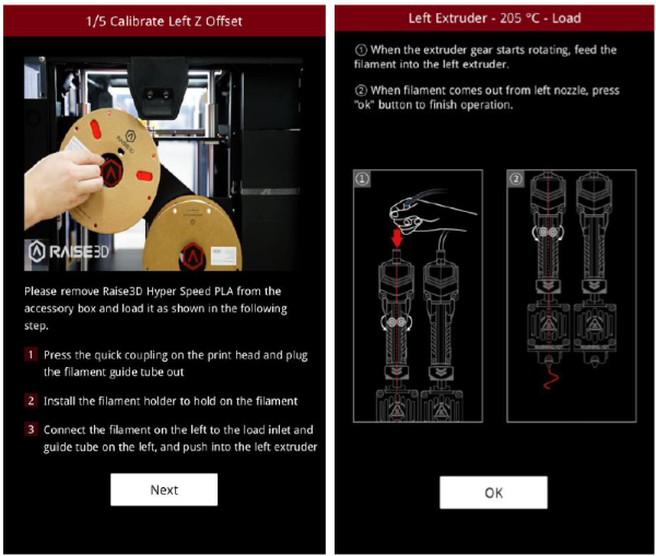
3. After adjusting the distance between the nozzle and the build plate, follow the prompt on the screen to install and load the filament.
Note: Two spools of Raise3D Hyper Speed PLA filament are used for calibration in this tutorial.
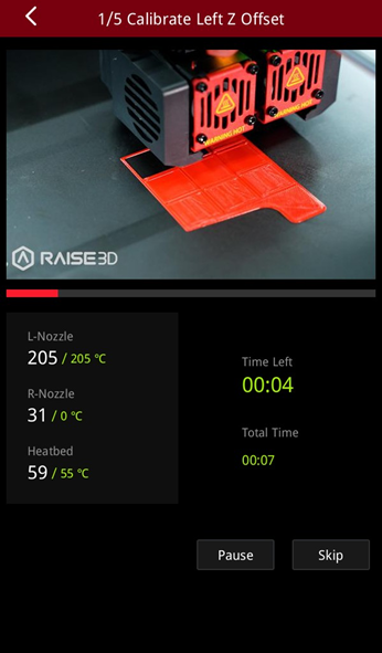
4. After loading the filament, the printer will start printing a 9-square calibration model. Wait for the model to finish printing.
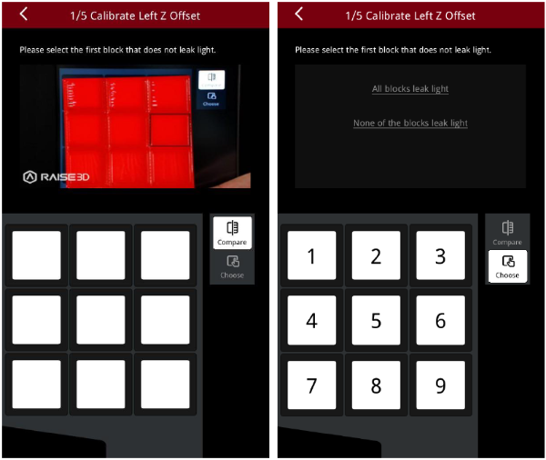
5. After the model is printed, compare the model with the on-screen example. Hold the model up against a light and select the first block that doesn’t leak light. The printer will automatically adjust the offset value of the left nozzle.
Note: If all the blocks leak light or do not leak light, it means that there may be deviations when measuring the distance between the build plate with a feeler gauge, and it is necessary to recalibrate by selecting the corresponding scenario.
●If all the blocks leak light, the distance between the nozzles and the build plate is too large. Select "All blocks leak light" and the machine will lower the nozzle and recalibrate.
●If all the blocks do not leak light, the distance between the nozzle and the build plate is too small. Select "None of the blocks leak light" and the machine will lift the nozzle and recalibrate.
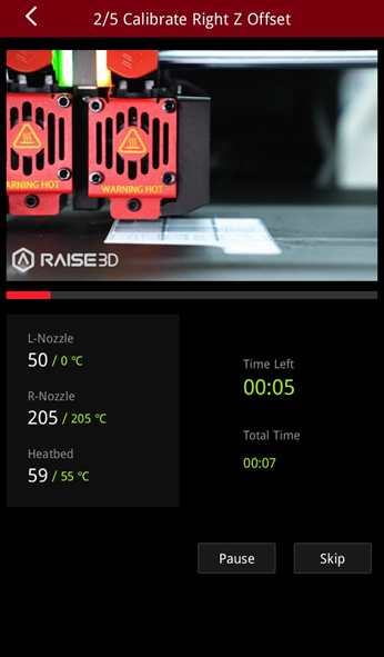
1. Enter the Right Z Probe Offset. Make sure that the nozzle and build plate are clean.
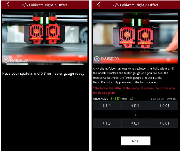
2. With a 0.3 mm feeler gauge, adjust the distance between the nozzle and the build plate according to the prompts on the screen. Make sure that you can feel some resistance as the feeler gauge moves between the nozzle and build plate. Do not press hard on the build plate.
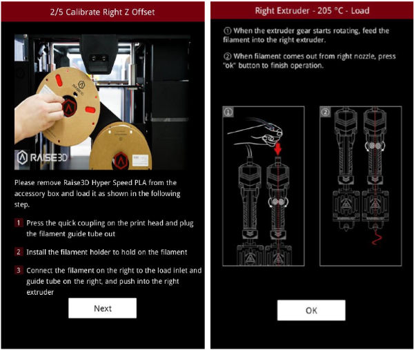
3. After adjusting the distance between the nozzle and the build plate, follow the prompt on the screen to install and load the filament.
Note: Two spools of Raise3D Hyper Speed PLA filament are used for calibration in this tutorial.
4. After loading the filament, the printer will start printing a 9-square calibration model. Wait for printing to complete.
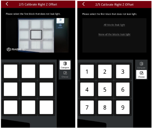
5. After the model is printed, compare the model with the on-screen example. Hold the model up against a light and select the first block that doesn’t leak light. The printer will automatically adjust the offset value of the right nozzle.
Note: If all the blocks leak light or do not leak light, it means that there may be deviations when measuring the distance between the build plate with a feeler gauge, and it is necessary to recalibrate by selecting the corresponding scenario.
●If all the blocks leak light, the distance between the nozzles and the build plate is too large. Select "All blocks leak light" and the machine will lower the nozzle and recalibrate.
●If all the blocks do not leak light, the distance between the nozzle and the build plate is too small. Select "None of the blocks leak light" and the machine will lift the nozzle and recalibrate.
1. The purpose of this step is to calibrate the flatness of the build plate. The printer will automatically detect 64 points on the build plate and adjust the flatness of the build plate.
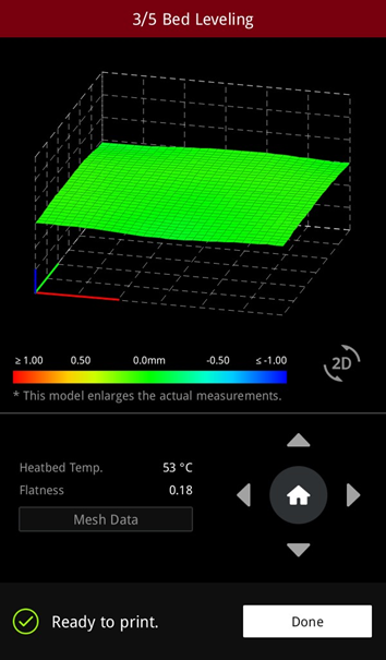
2. After the build plate is leveled, a visualized leveling result is displayed.
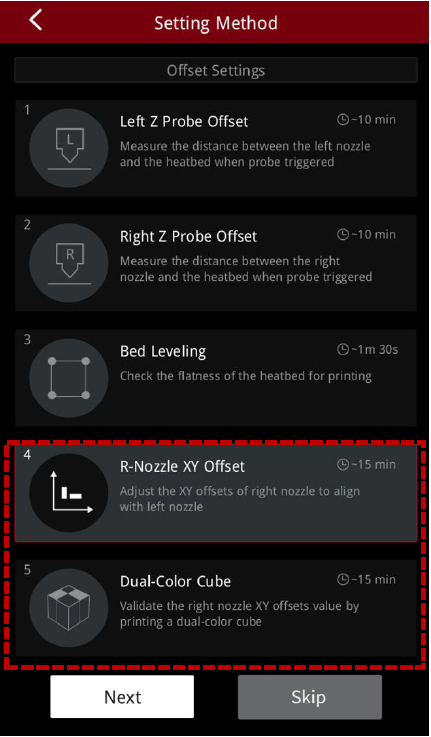
1. The purpose of this step is to calibrate the XY offset of the right nozzle so that it aligns with the left nozzle. The printer will heat up automatically and print two test models.
Note: This calibration can only be performed if both the left extruder and the right extruder are loaded with PLA filaments, otherwise this step cannot be performed. In this tutorial, the left and right extruders are loaded with Raise3D Hyper Speed PLA filaments.
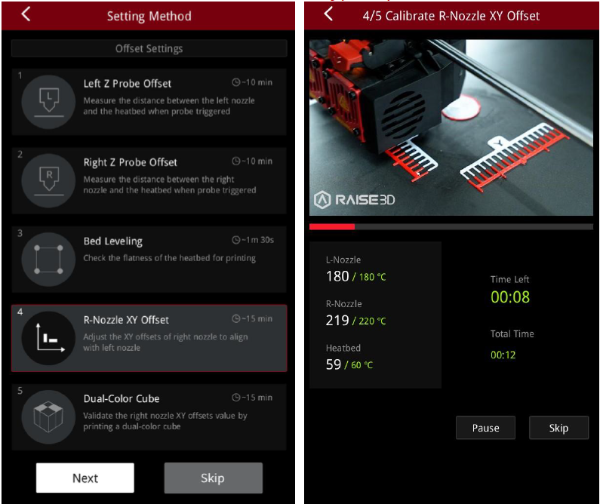
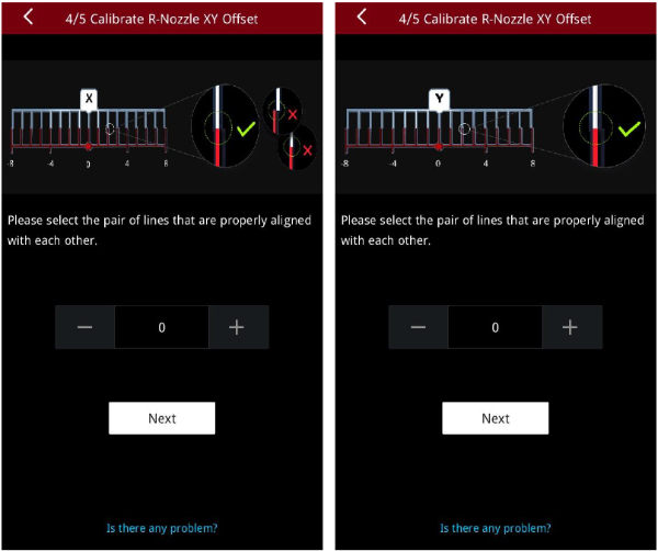
2. After printing, according to the instructions on the screen, select a pair of lines that are completely aligned on the X model and the Y model respectively. As exampled in the figure below, the corresponding number to the pair of aligned lines on the X model is 1, and the corresponding number to the pair of aligned lines on the Y model is 2.
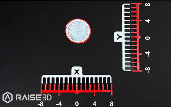
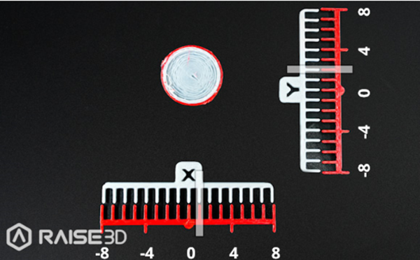
3. Input the serial number on the screen. The printer will automatically calibrate the XY Offset of the right nozzle.
1. This step aims to validate the XY offset value of the right nozzle by printing dual-color cubes.
Note: This calibration can only be performed if both the left extruder and the right extruder are loaded with PLA filaments, otherwise this step cannot be performed. In this tutorial, the left and right extruders are loaded with Raise3D Hyper Speed PLA filaments.
2. After printing, please compare the printed dual-color cube with the sample graphic on the screen, and check whether there is an obvious gap between the color blocks.
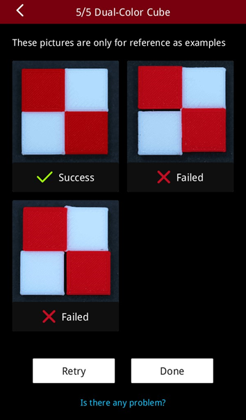
3. If there is no gap between the color blocks, it means that the XYZ direction offset value of the right nozzle is within a reasonable range. Please tap "Done" to complete the 5-step Offset Calibration.
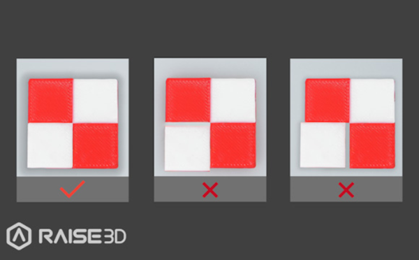
4. If there is a gap between the color blocks, please tap "Retry" and re-run the 4th and 5th steps of the 5-step Offset Calibration to recalibrate the XY offset value of the right nozzle.
After the 5-step calibration is completed, you can start your first high-speed print!

1.Download the latest version from: https://www.raise3d.com/download/.
2.Open the installer and select the installation language. Select the appropriate ideaMaker install location and click “Next”.
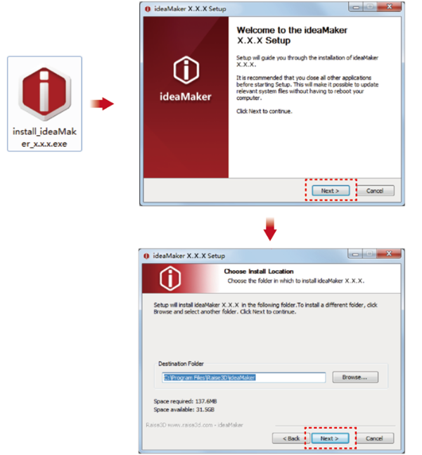
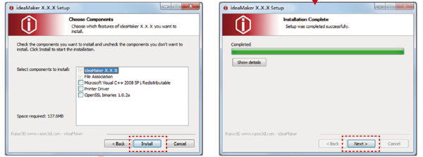
3.Follow the instructions provided by the guide and click “Install”. After the installation is complete, click “Next” to go to the next step.
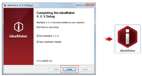
4.Click “Finish” and ideaMaker is installed.

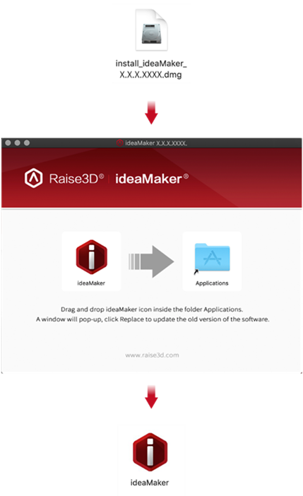
1.Download the latest version from: https://www.raise3d.com/download/.
2.Drag the ideaMaker icon (left) into the Application folder on the right side.
1. After downloading and installing ideaMaker onto your computer, import a model into ideaMaker.
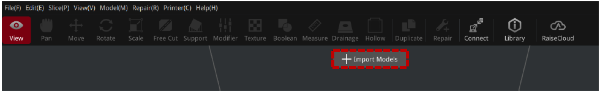
2. Select the appropriate Raise3D Pro3 HS or Pro3 Plus HS printer. Select extruder filament templates.
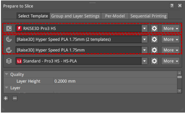
3. Select a desired slicing template for the filament.
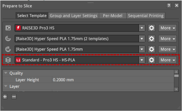
1) The templates will be marked L1/L2 according to their values of velocity, acceleration, and volumetric flow rate within their settings.
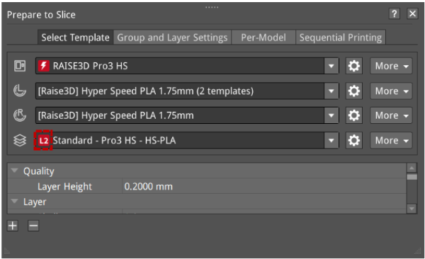
2) ideaMaker will judge all parameters related to speed, acceleration, and flow rate in the current template settings. As long as one parameter value reaches L1 or L2, after the template is saved, it will add L1 or L2 labels to the template (L0 will not be displayed).
Parameter | Nozzle | Speed Range | |||
Acceleration(mm/s2) | 0.6 mm | x <= 1500 | 1500 < x <= 5000 | 5000 < x <= 10000 | x > 10000 |
0.4 mm | |||||
Speed(mm/s) | 0.6 mm | x <= 100 | 100 < x <= 150 | 150 < x <= 350 | x > 350 |
0.4 mm | |||||
Volumetric Flow Rate(mm3/s) | 0.6 mm | x <= 10 | 10 < x <= 25 | 25 < x <= 40 | x > 40 |
0.4 mm | 10 < x <= 15 | 15 < x <= 30 | x > 30 | ||
Label Display | L0 (no display) | L1 | L2 | L0 (no display) | |
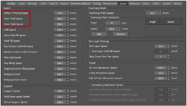
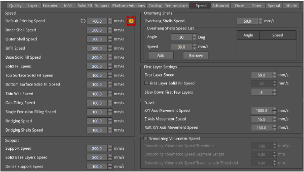
The speed judgment includes Default Printing Speed, Inner Shell Speed, and Outer Shell Speed. Click the "Edit  " icon to enter the advanced settings of the template. The speed judgment items are shown in the red box below.
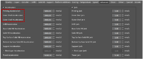
Acceleration judgment includes Printing Acceleration, Inner Shell Acceleration, and Outer Shell Acceleration, as shown in the red box below.
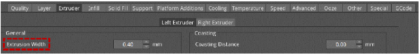
Volumetric flow rate calculation formula: Volumetric Speed = Layer Height * Extrusion Width * Speed
The volumetric flow rate is determined by the Layer Height, Extrusion Width, and Speed.
Volumetric flow rate judgment includes Default Printing Speed, Inner Shell Speed, and Outer Shell Speed, as shown in the red box below.


3) In ideaMaker, Raise3D filaments have threshold limits for speed, acceleration, and volumetric flow rate in Standard Mode and Hyper Speed Modes respectively, and if each speed exceeds the threshold, ideaMaker will display an alert.
When the speed, acceleration, and volumetric flow rate exceed the threshold, a yellow exclamation mark reminder is given, and an explanation is given when the mouse hovers over it.
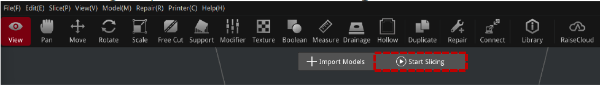
4. After reviewing the parameters, click "Start Slicing" to slice the model.
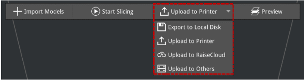
5. After slicing, you can export the file to the local disk and then upload it to the printer, or you can upload it directly to the Pro3 HS series printer to start your Hyper Speed printing.
Open the side door of the printer. Place two filament holders on the installation points.
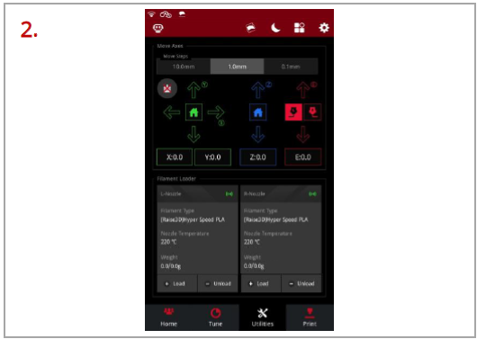
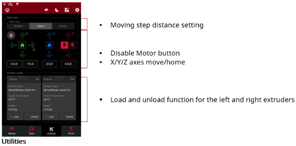
Select the “Utilities” tab at the bottom of the screen. Tap “Load” for the left or right nozzle.
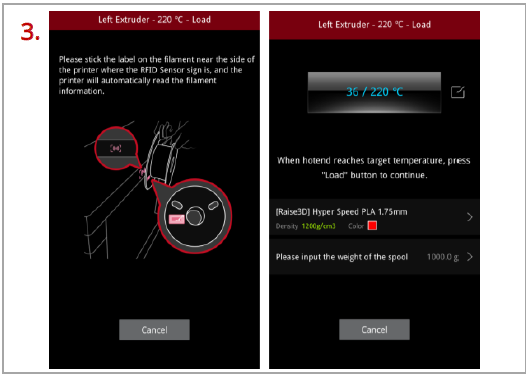
Following the prompts on the screen, take out a roll of Raise3D Hyper Speed PLA. Attach the tag on the filament to the RFID sensor above the holders, and the printer will automatically read the filament information.
Important: These instructions are based on the properties of Raise3D Hyper Speed PLA filament. The Pro3 HS series printers come with two spools of Raise3D Hyper Speed PLA. We recommend using Raise3D Hyper Speed PLA for testing and initial setup.
Install the filament on the holder.
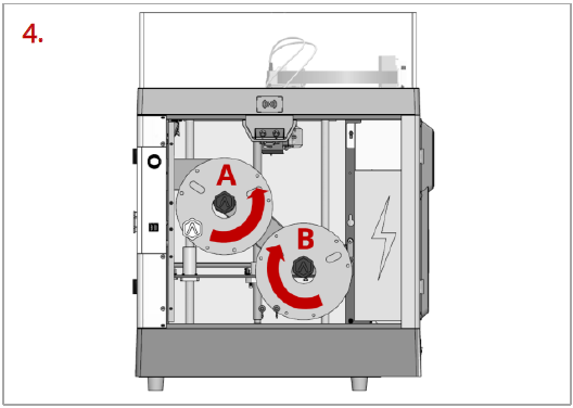
Note: As shown in the left figure, if the filament is installed at the point A, it is recommended to place the filament in a clockwise direction; if the filament spool installed at the point B, it is recommended to place the filament spool in a counterclockwise direction.
Placing the filaments in the suggested directions, as shown in the figure, can make feeding filaments smoother.
Press and hold the metal quick connector on the extruder and pull out the filament guide tube.
Find the tip of the filament. Pass the filament into the left or right inlet until the tip of the filament is completely through the guide tube.
Note: Here we take the left extruder as an example, because the operation of the left extruder is the same as that of the right extruder. The left and right inlets are as shown in the figure, please do not mix them up.
You can also feed the filament from an external filament box through the external left/right inlets located on the right side.
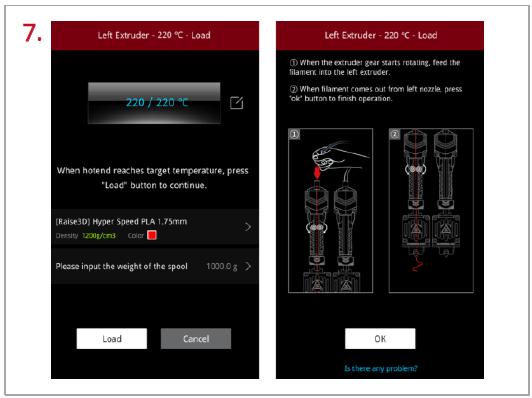
When the printer reaches the target temperature, tap “Load”. The extruder gear will start to rotate. Gently push the filament into the extruder. When the filament is extruded out from the nozzle, tap “OK” to complete the loading. Insert the guide tube back into the quick connector.
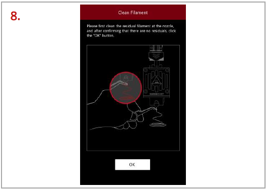
Clean the residual filament at the nozzle. Tap “OK” and loading filament is complete.
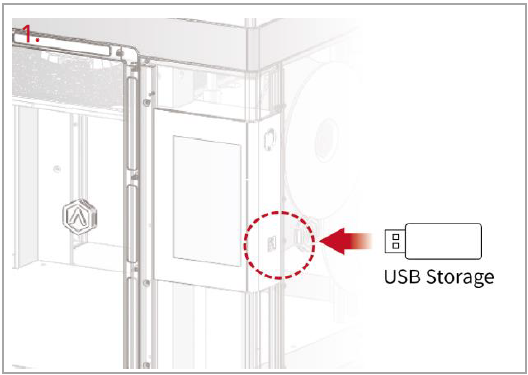
Insert the USB device that contains your sliced model files (.gcode or .data) into the USB port on the side of the touch screen.
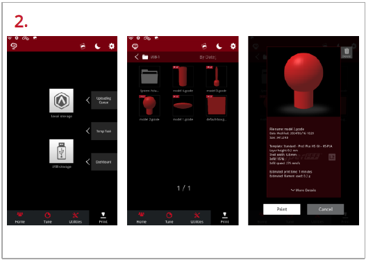
Select the “Print” tab at the bottom of the touch screen and choose “USB Storage” to open the file storage path. Select your sliced model file to check the printing parameters and settings. Tap “Print” to start printing the model.
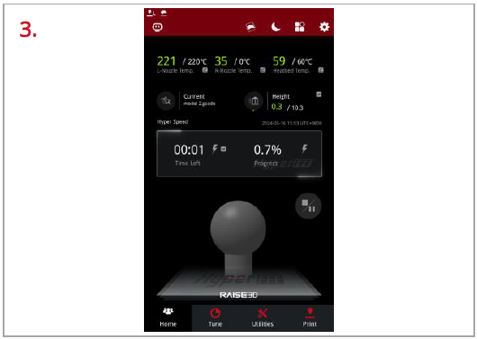
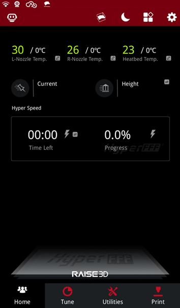
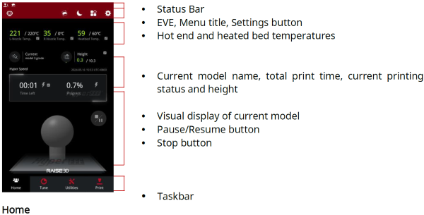
During the printing process, you can check the printing status from the “Home” interface on the touch screen, including the remaining printing time and other parameters.
Note: The model image will only be displayed on the touch screen when the file is sliced by ideaMaker, and the .data file is exported to the USB drive or the .data file is uploaded to the printer.
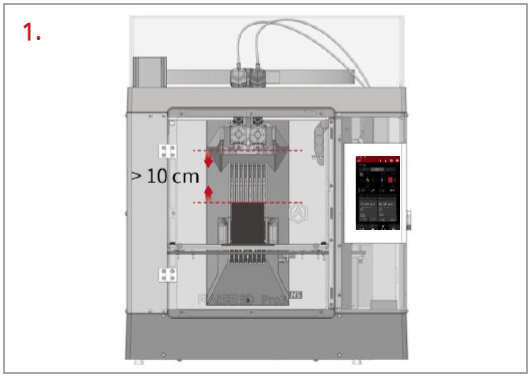
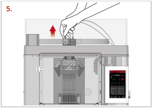
Make sure the printer is idle, and there is at least a 10 cm gap between the printed model’s top and the nozzle. This is to prevent the nozzle from scratching the model or damaging the model when it is taken out.
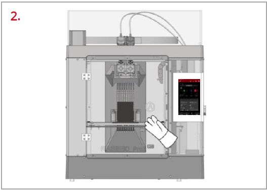
Wait for the build plate and nozzles to cool down to room temperature before removing any models. If you want to remove the model before they have sufficiently cooled down, please wear the heat-resistant gloves from the attached accessory box.
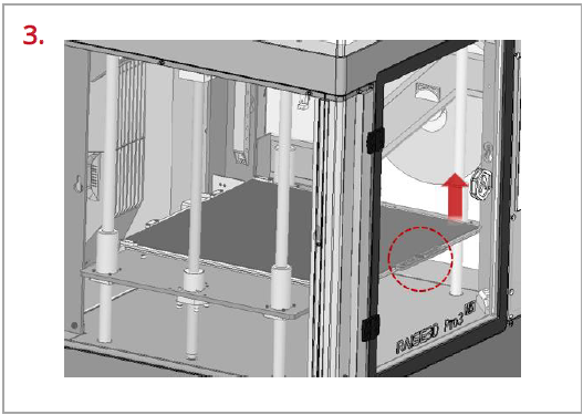
Hold the red protective handle (as shown in the red circle) to gently lift the printing surface, and then take out the printing surface from the printer.
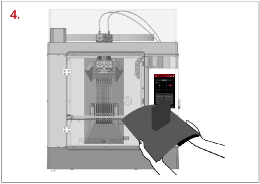
Bend the printing surface repeatedly along the longer span of the model until the model is detached from the printing surface.
Note: Do not directly touch the edge of the printing surface to avoid injury. Do not over-bend the printing surface to avoid damaging the plate or causing the plate to bounce off from hands.
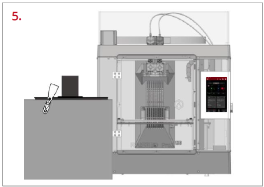
If the model is not entirely loose or if you feel the model is hard to remove after bending the printing surface several times, use the spatula from the attached accessory box to remove it.
Use one hand to hold the printing surface and use the other hand to scrape off the model with the spatula.
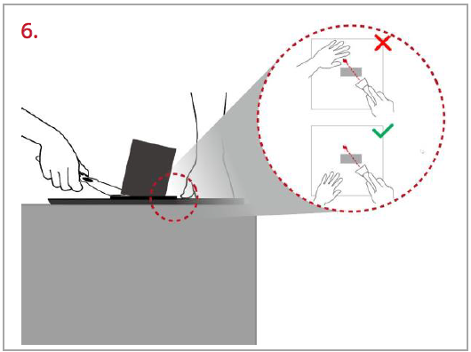
Note: We recommend placing the spatula above the plate and inserting it into the gap between the model and the plate. If the model is printed with the Raft, it is better to scrape the prints along the infill direction of the Raft. Do not put your hands in front of the spatula to prevent injury.
After the model is removed, the printing surface needs to be reinstalled onto the build plate. Gently put the printing surface to its original position by holding the red protective handle. Place the printing surface against the four side strips (as shown in the red circles), and then attach the entire printing surface to the build plate.
If you run into any issues during this guided setup, please contact our expert technicians by creating a ticket online at https://help.raise3d.com/support/tickets/new.


