
Tools:
① 0.3mm feeler gauge card
② Raise3D Premium PLA filaments (*2)
A feeler gauge card was included within the accessories kit box that originally shipped with the printer.
When do I need to recalibrate the nozzle height?
Recalibrate the nozzle height when you:
1. Exchange the left interchangeable hotend with the right one;
2. Replace a new interchangeable hotend;
3. Replace a component on the hotend, such as the heat sink, the nozzle, and the throat tube;
No need to recalibrate the nozzle height when you:
1. Remove one interchangeable hotend from the extruder;
2. Replace the cooling fan or the extruder controller board.
How to calibrate the nozzle height?
1. Ensure that 2 spools of Raise3D Premium PLA filaments are loaded into your printer, and that the printer can extrude the filament without issue. Refer to the Pro3 Series-How to Load and Unload the filament in the Support Center.
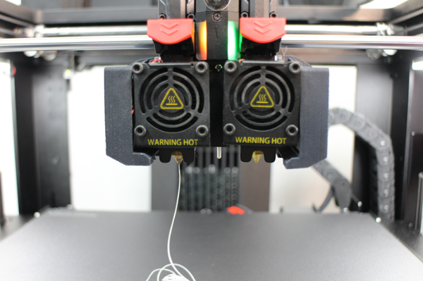
Figure 1 Verify that your printer can extrude filament without issue.
2. Select the "Setting" icon in the upper-right corner to enter the setting interface.
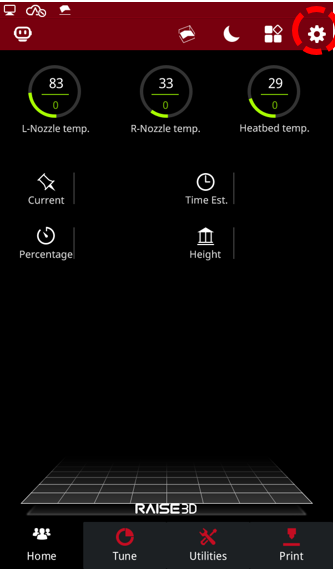
Figure 2 Enter the setting interface.
3. Select "Maintenance" on the "Machine" tab.
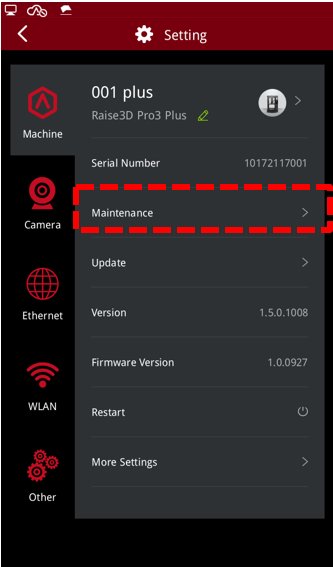
Figure 3 Enter Maintenance.
4. Select "Offset Calibration".
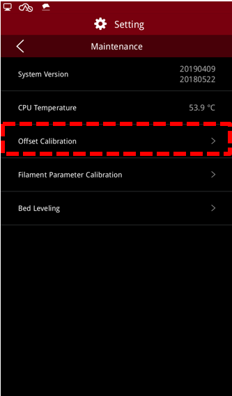
Figure 4 Enter Offset Calibration.
5. Ensure that your printer has met all the requirements on the screen, and then select "Start".
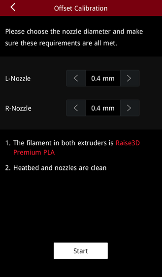
Figure 5 Ensure that your printer has met all the requirements.
6. You will enter the 5-step Offset Calibration. You need to run Step 1 and Step 2. Step 1 is Left Z Probe Offset, and Step 2 is Right Z Probe Offset. These steps are aimed at calibrating the height of the left and right nozzle relative to the build plate.
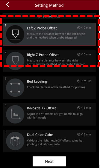
Figure 6 Run the Left Z Probe Offset and Right Z Probe Offset.
7. Follow the on-screen instructions to ensure that both nozzles and the build plate are clean, and then select "Next" to proceed.
Figure 7 Verify that both nozzles and the build plate are clean.
8. After the build plate stops moving, place a 0.3 mm feeler gauge card between the left nozzle tip and the build plate. Align the frosted dot of the feeler gauge with the nozzle tip, and carefully move the feeler gauge about to feel for a presence of friction.
Note: Do not press the build plate forcibly when moving the feeler gauge. External pressure on the build plate may cause the test value to deviate.
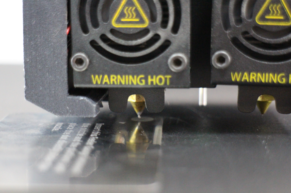
Figure 8 Align the rough point of the feeler gauge with the nozzle tip to test the height.
9. If you can feel resistance between the feeler gauge and the nozzle tip, then it is at the best height.
However, if you cannot feel resistance, press an upward arrow value amount on the touchscreen to adjust the height of the build plate closer to the nozzle. After a suitable amount of friction is felt with the feeler gauge card, press the "Next" button to proceed.
Note:
1. The upward arrow is to decrease the distance between the build plate and the nozzle. The downward arrow is to increase the distance between the build plate and the nozzle.
2. When setting an appropriate gap distance, you should be able to remove the feeler gauge without disturbing the nozzle.
If introducing the feeler gauge displaces the nozzle, it is a sign that the build plate is too close, which can result in printing issues.
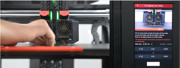
Figure 9 Adjust the height of the build plate.
10. The printer will automatically heat up and print multiple test lines, unless the machine is configured for Hyper Speed printing. The calibration print for Hyper Speed consists of 9 squares arranged in a 3x3 configuration. Follow the on-screen instructions to successfully complete the Hyper Speed calibration.
With non-Hyper Speed, after the test lines are printed, compare the test lines against the example on the screen. The printer will ask you to select the first line that is completely twisted/coiled.
Figure 10 The printer will automatically print multiple test lines (non-Hyper Speed printer)
11. For example, line 9 is a completely twisted/coiled line. Select “9” and then select "Next" to enter the next step.
Note: If all lines are twisted/coiled at this time, or there is no twisted/coiled line, please press the appropriate button below to navigate to the corresponding solution.
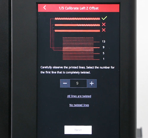
Figure 11 Select a completely twisted/coiled line.
12. At this point, the printer has automatically adjusted to the left nozzle's most suitable height, and will display the current value. In our example, the height of the left nozzle is now 2.57mm.
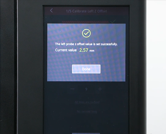
Figure 12 The printer has automatically adjusted to the left nozzle's most suitable height.
13. Next, you need to calibrate the height of the right nozzle, similarly to the left nozzle, referencing the above steps.
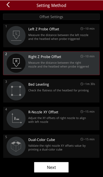
Figure 13 Calibrate the Right Z Probe Offset.
