
Tool:
① Raise3D Premium PLA Filament (*2)
(Different colors would be helpful for this calibration procedure)
1. Ensure that two spools of Raise3D Premium PLA filaments are loaded into the printer, and that the printer can extrude the filament without issue. Please review Pro3 Series-How to Load and Unload the filament in the Support Center to learn how to load filament successfully.
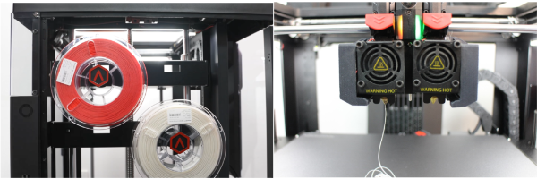
Figure 1. Load the filament into the printer.
2. Select the "Setting" gearwheel icon in the upper-right corner to enter the Setting interface.
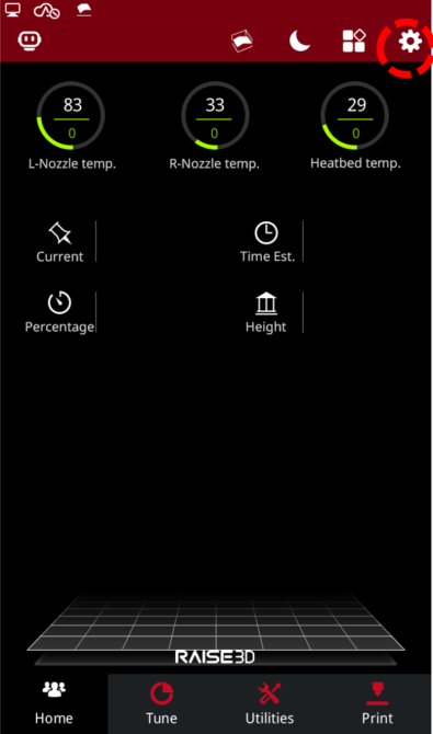
Figure 2. Enter the Setting interface.
3. Select "Maintenance" on the "Machine" tab.
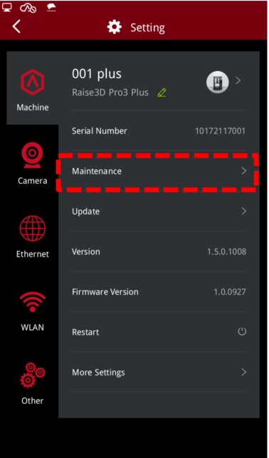
Figure 3. Enter the Maintenance interface.
4. Select "Offset Calibration".
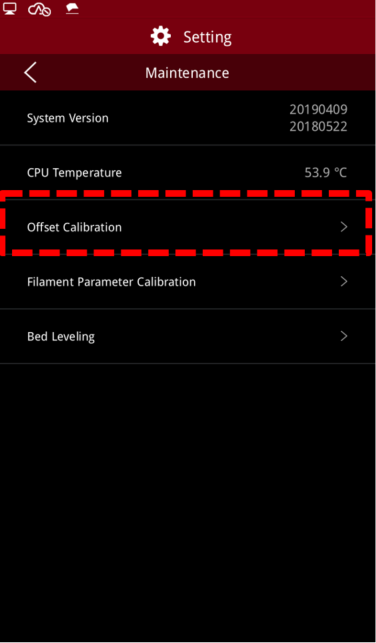
Figure 4. Enter the Offset Calibration.
5. Verify that the printer meets all requirements shown on the touchscreen, and then select "Start".
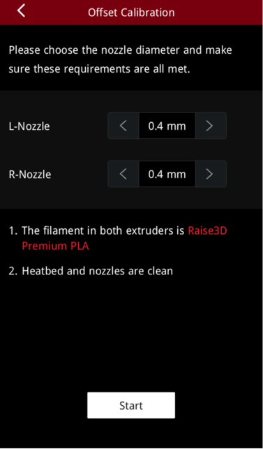
Figure 5. Ensure that the printer meets all the requirements.
6. Select Step 4: R-Nozzle XY Offset. Then, select "Next". This step will allow you to calibrate the XY offset of the right nozzle to align it with the left nozzle.
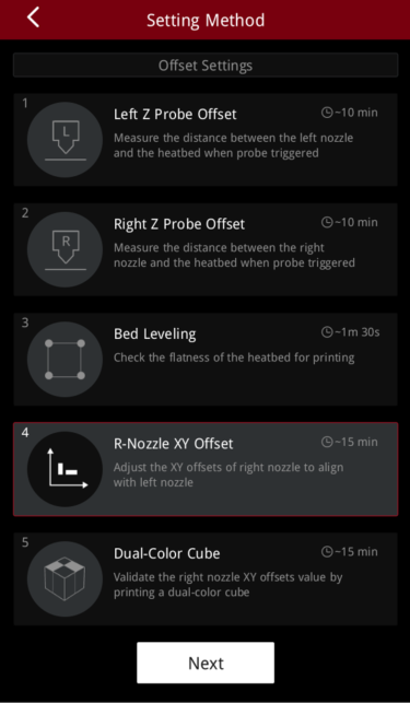
Figure 6. Run Step 4: R-Nozzle XY Offset.
7. The printer will automatically heat up and print two dual-color calibration models.
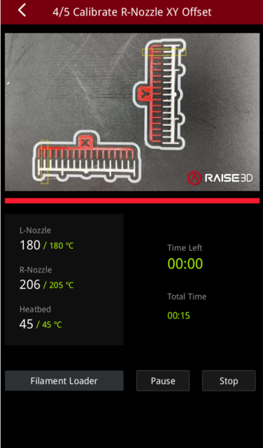
Figure 7. The printer will automatically heat up and print two models.
8. Once printing is complete, select a pair of straight lines that are aligned on both the X model and Y model, according to the instructions on the touchscreen. As seen below, the number associated with the pair of lines that are aligned on the X model is -1. The number associated with the pair of lines that are aligned on the Y model is 6.
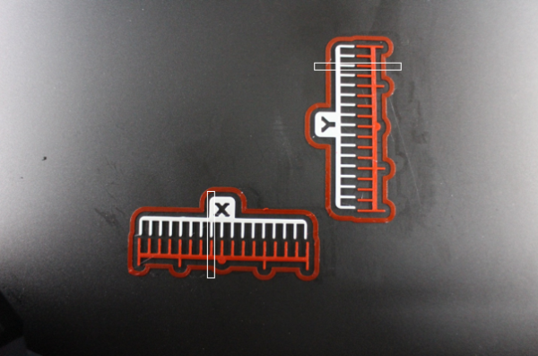
Figure 8. Select a set of straight lines that are aligned, on both the X and Y model, respectively.
9. Select the appropriate corresponding number on the touchscreen. Then select "Next".
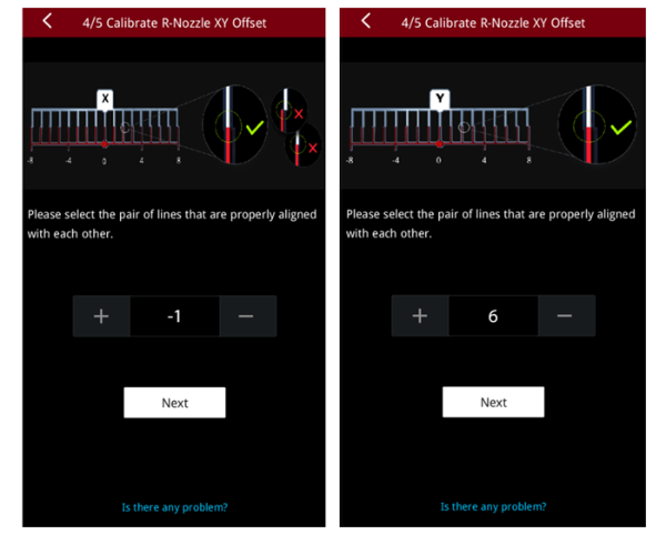
Figure 9. Select the appropriate corresponding number on the touchscreen.
10. Now, the printer has calibrated the XY offset of the right nozzle, relative to the left nozzle, and displays the current calibration values, exampled below.
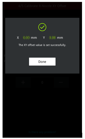
Figure 10. The printer has calibrated the XY offset of the right nozzle.
11. Next, continue to Step 5, which is designed to validate the XY offset values by printing a small dual-color cube. Select “Dual-Color Cube”, then select "Next". The printer will start printing the model.
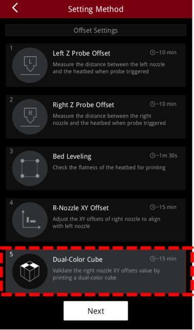
Figure 11. Print a dual-color cube to validate the XY offset values.
12. When the printing is completed, example cubes will appear on the touchscreen. Please compare your printed dual-color cube with the examples on the touchscreen and check for gaps between the smaller squares.
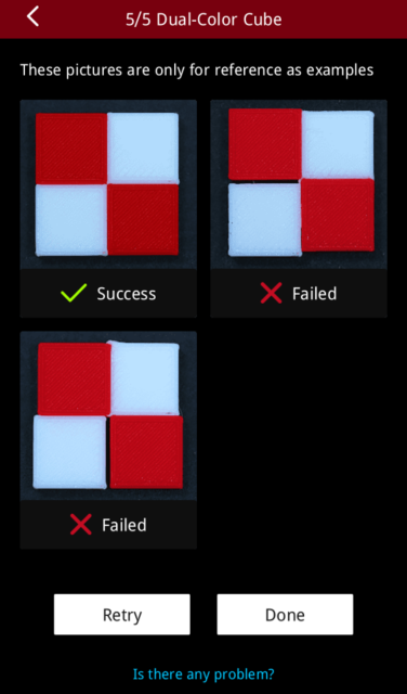
Figure 12. Compare your dual-color cube with the examples on the touchscreen.
1) If there is no gap between the small colored squares, it means that the offset values in the XY direction of the right nozzle are successful. Please press "Done" to conclude and exit the 5-step offset calibration.
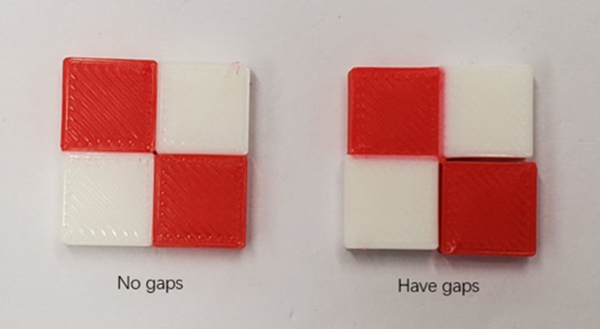
Figure 13. Carefully look for any gaps between the small colored squares.
2) If there are gaps between the small colored squares, please select "Retry" and re-run Step 4 and Step 5 to recalibrate the XY offset values of the right nozzle.
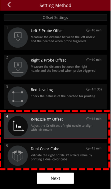
Figure 14. Re-run Step 4 and Step 5 to recalibrate the XY offset value.
