
Tools:
① 2mm hex wrench
② 2.5mm hex wrench

A. Remove the Flat Cable.
1. Turn off the printer and cut off the power.

Figure 1 Turn off the printer and cut off the power.
2. Remove the back cover and remove the 7 screws. 6 of the screws require a 2mm hex wrench to remove them and are indicated with a red circle in the image below. One of the screws requires a 2.5mm hex wrench to remove it and is indicated with the green circle in the image below.
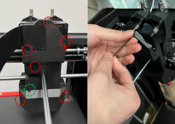
Figure 2 Remove the back cover and remove the 7 screws.
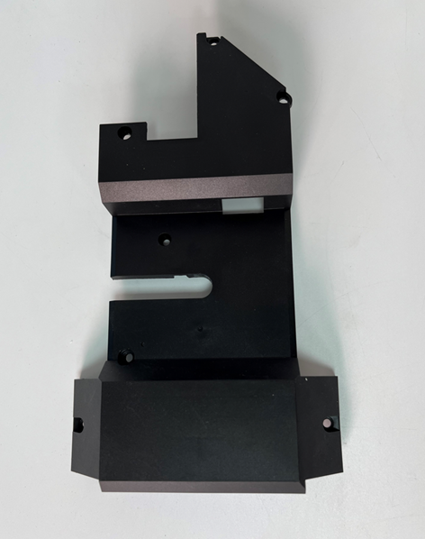
Figure 3 Remove the back cover.
2)Remove the 3 screws with the 2 mm hex wrench, then remove the flat cable cover.
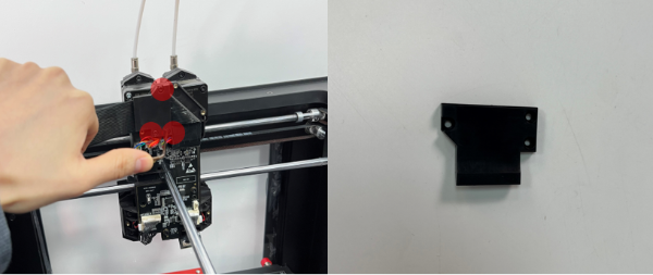
Figure 4 Remove the 3 screws with the 2 mm hex wrench, then remove the flat cable cover.
3)Locate and press the buckle on the flat cable connector then remove the flat cable connector.
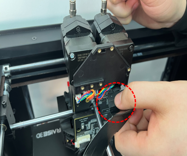
Figure 5 Locate and press the buckle on the flat cable connector and remove the flat cable connector.
4)Remove the 4 screws with the 2.5mm hex wrench on the back cover, then remove the back cover.
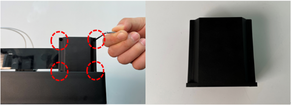
Figure 6 Remove the 4 screws with the 2.5mm hex wrench on the back cover, then remove the back cover.
5)Remove the 4 screws on the spacer of the front cover with the 2.5mm hex wrench, then remove the spacer.
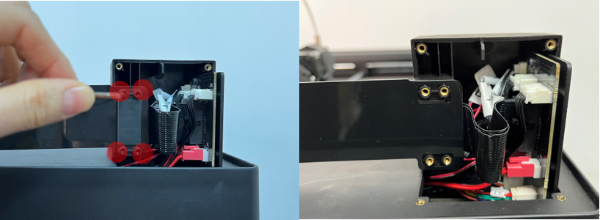
Figure 7 Remove the 4 screws on the spacer of the front cover with the 2.5mm hex wrench, then remove the spacer.
6)Remove the 2 screws on the spacer of the front cover with the 2.5mm hex wrench, and remove the front cover.
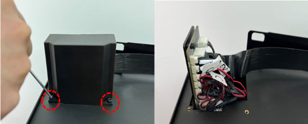
Figure 8 Remove the 2 screws on the spacer of the front cover with the 2.5mm hex wrench, then remove the front cover.
7) Locate and hold the buckle on the flat cable connector. Pull out the flat cable connector. Then remove the flat cable and the PC cable support.
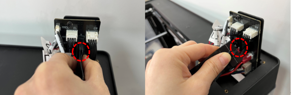
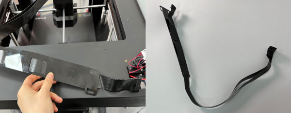
Figure 9 Locate and hold the buckle on the flat cable connector. Pull out the flat cable connector. Then remove the flat cable and the PC cable support.
8)Remove the flat cable from the PC cable support.
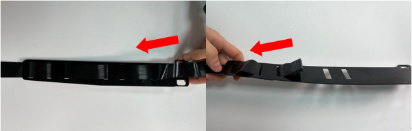
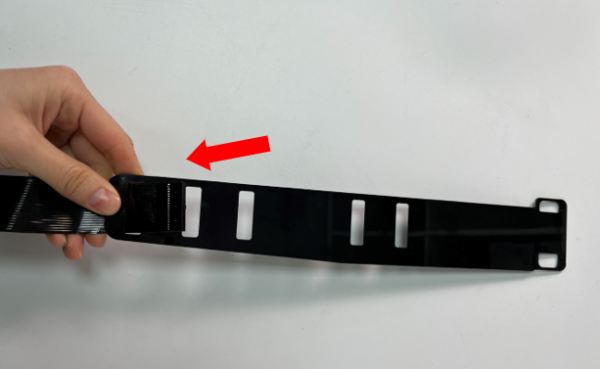
Figure 10 Remove the flat cable from the PC cable support.
B. Install the Replacement Flat Cable.
1. Install the replacement flat cable to the PC cable support.
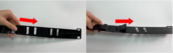
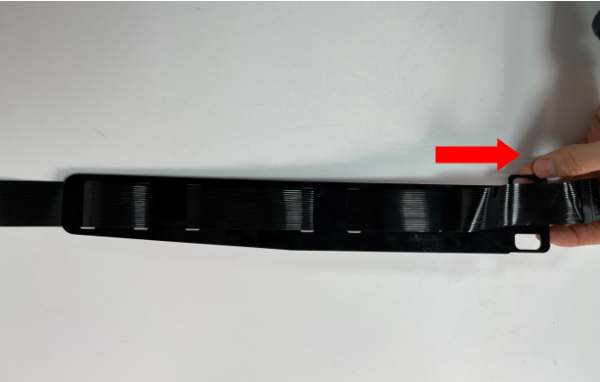
Figure 11 Install the replacement flat cable to the PC cable support.
2. Locate the position and press the buckle on the flat cable connector, and tightly insert it into the slot.
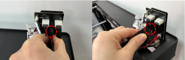
Figure 12 Locate the position and press the buckle on the flat cable connector, and tightly insert it into the slot.
3. Install the 2 screws on the spacer of the front cover with the 2.5 mm hex wrench, and install the front cover.
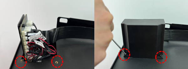
Figure 13 Install the 2 screws on the spacer of the front cover with the 2.5 mm hex wrench, and install the front cover.
4. Install the PC cable support and the spacer. Put the PC cable support on the front cover, and put the spacer on it. Install the 4 screws on the spacer of the front cover with the 2.5 mm hex wrench, and install the spacer.
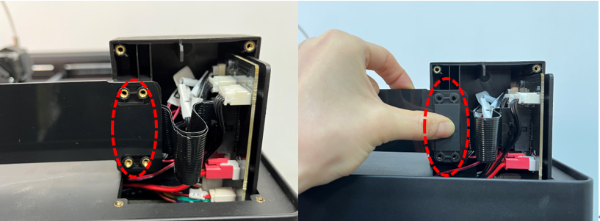

Figure 14 Install the 4 screws on the spacer of the front cover with the 2.5 mm hex wrench, and install the spacer.
5. Put the back cover in place. Install the 4 screws on the back cover with the 2.5 mm hex wrench.
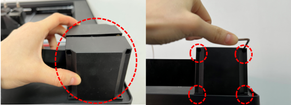
Figure 15 Put the back cover in place. Install the 4 screws on the back cover with the 2.5 mm hex wrench.
6. Locate and press the buckle on the flat cable connector, insert it into the slot, and fold the flat cable along the shape of the extruder.
Note: Pay attention to fold from top to left when folding. The overlap is a right triangle, as circled in the Figure below. Pay attention to the folding sequence to avoid cable stranding.

Figure 16 Locate and press the buckle on the flat cable connector, insert it into the slot, and fold the flat cable along the shape of the extruder.
7. Install the 3 screws with the 2 mm hex wrench, and install the flat cable cover.
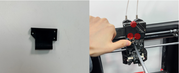
Figure 17 Install the 3 screws with the 2 mm hex wrench, and install the flat cable cover.
8. Install the back cover and install the 7 screws. 6 of the screws require a 2 mm hex wrench to remove them and are indicated with a red circle in the image below. One of the screws requires a 2.5mm hex wrench to remove it and is indicated with the green circle in the image below.
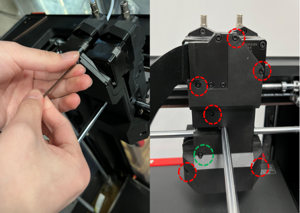
Figure 18 Install the back cover and install the 7 screws.
D. Check If the Extruder Runs Normally After Replacing the Flat Cable.
1. Find the power switch at the bottom right on the back of the printer and turn on the switch.
2. Check if the extruder operates normally by performing the steps of loading the filament.
1)Select the “Utilities” tab on the screen.
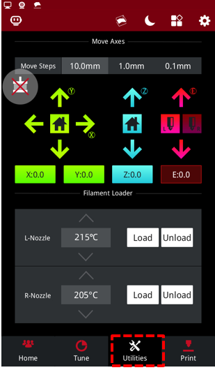
Figure 19 Enter the “Utilities” tab.
2)Set the temperature of the nozzle to the proper unloading temperature. For example, the Raise3D PLA default loading temperature is 215℃. Here, we use the left nozzle as an example of how to perform this procedure. We set the left nozzle temperature to 215℃.
Note: The recommended loading temperature for other filaments is typically 5-10℃ higher than its common printing temperature.
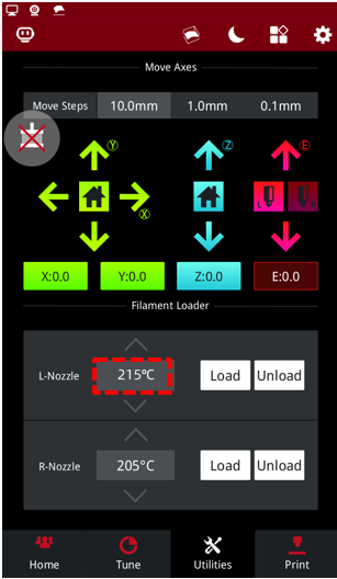
Figure 20 Set the temperature of the nozzle to the proper unloading temperature.
3)Select the “Load” button and the printer will begin to heat. When it reaches the target temperature, select "Load".
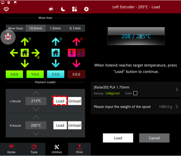
Figure 21 Load the filament.
4)The extruder gear will start to rotate. Gently push the filament into the extruder. When the filament extrudes from the nozzle, click "OK" to complete the loading.

Figure 22 Gently push the filament into the extruder.
5)Confirm that the filament can extrude evenly, and then insert the guide tube back into place. Now that the printer runs normally after replacing the flat cable, you can start printing your model.
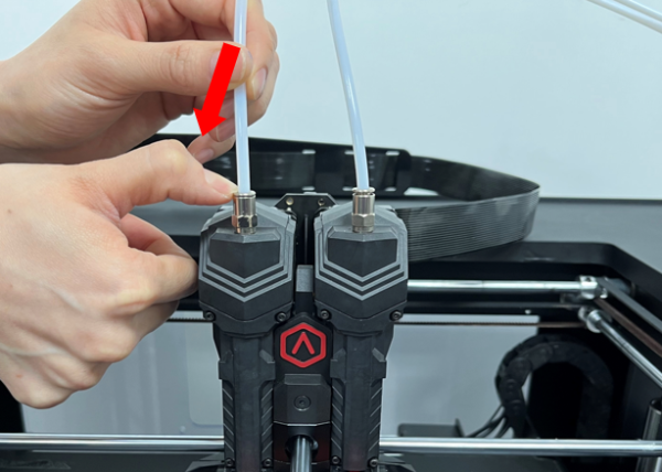
Figure 23 The printer runs normally, insert the guide tube back into place.
[ Pro3 Series –How to Replace the Extruder – V1.0 ]
-End-
