
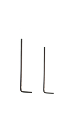
Tools:
①2mm hex wrench
②2.5mm hex wrench
A. Move the Print Head to a Position Where You Can Easily Operate It
Adjust the print head to a position where you can easily operate.
1. Select the “Utilities” tab on the screen.
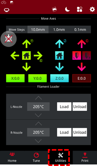
Figure 1 Select the “Utilities” tab on the screen.
2. Select the “Unlock” button on the upper left corner on the screen.
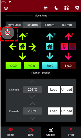
Figure 2 Select the “Unlock” button.
3. Push the print head carrier to move the extruder to a position suitable for operation.
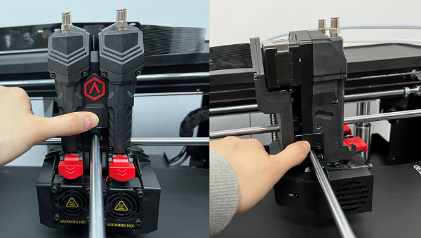
Figure 3 Push the print head carrier to move the extruder to a position suitable for operation.
B. Remove the PCB Cover
Remove the PCB cover and remove the 7 screws from it. 6 of the screws require a 2mm hex wrench to remove them and are indicated with a red circle in the image below. One of the screws requires a 2.5mm hex wrench to remove it and is indicated with the green circle in the image below.
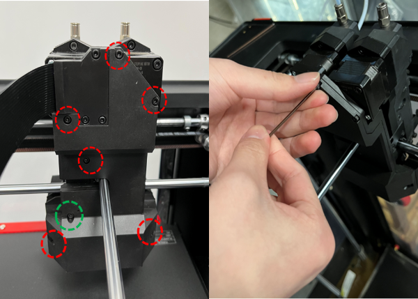
Figure 4 Remove the back cover and remove the 7 screws from it.
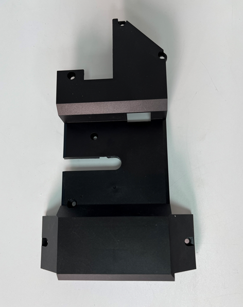
Figure 4 Remove the PCB cover.
C. Install the Replacement PCB Cover
Put the replacement PCB cover in place and tighten the 7 screws on it. 6 of the screws require a 2mm hex wrench to replace them and are indicated with a red circle in the image below. One of the screws requires a 2.5mm hex wrench to replace it and is indicated with the green circle in the image below.
Note: Pay attention to adjust the position when installing the PCB cover to avoid pressing the cables.

Figure 6 Put the PCB cover back in place and install it. Tighten 7 screws on the PCB cover.
[15.056.EN.1.020220517-Pro3 Series-How to Replace the PCB Cover]
-END-
