
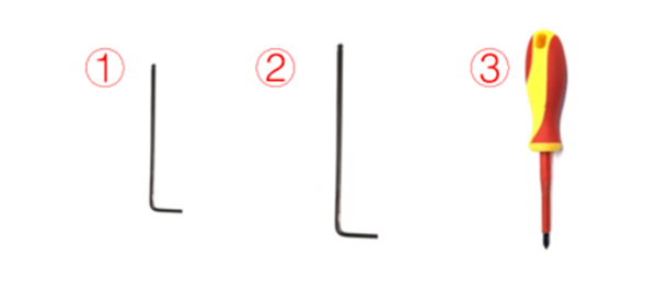
Tools:
①2.5mm hex wrench
②3mm hex wrench
③Phillips screwdriver
1. Unload the filament from the left and right extruders. The following is an explanation of how to unload the filament using the left extruder as an example.
1) Enter the “Utilities” interface.

Figure 1 Enter the “Utilities” tab.
2) Set the temperature of the nozzle to the proper loading temperature. For example, the Raise3D PLA default loading temperature is 215℃. Here, we set the left nozzle temperature to 215℃.
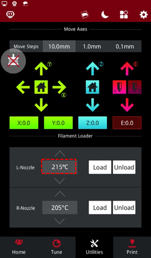
Figure 2 Set the temperature of the nozzle to the proper unloading temperature.
3) Select "Unload", and follow the instruction to unload the filament.
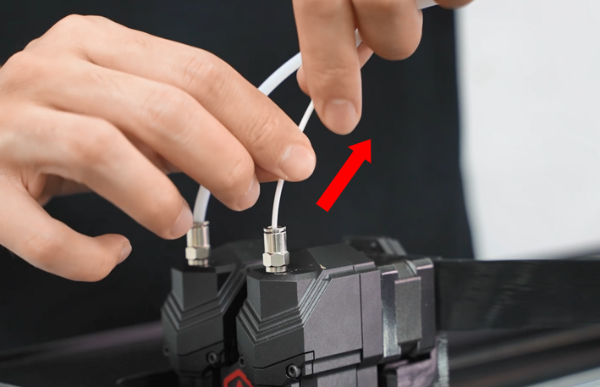
Figure 3 Unload the filament.
4) Gently pull the filament out of the extruder. After the filament is completely removed from the extruder, select "OK" on the screen to end the unloading.
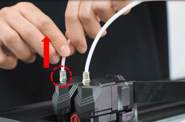
Figure 4 Gently pull the filament from the extruder.
1. When the filament is unloaded from both the extruders, press the metal connector of two extruders to pull out two filament guide tubes from the extruders.

Figure 1 Pull out two filament guide tubes from the extruders.
2. Turn off the printer and cut the power.
Figure 2 Turn off the printer and cut off the power.
3. Remove 8 screws on the top cover of the printer with a 2.5mm hex wrench.

Figure 3 Remove the 8 securing screws on the top cover.
4. Remove 11 screws that fix the top cover around the body of the printer with a Phillips screwdriver.

Figure 4 Remove 11 screws that fix the top cover.
5. Remove the 6 screws on the extruder adapter board box cover.
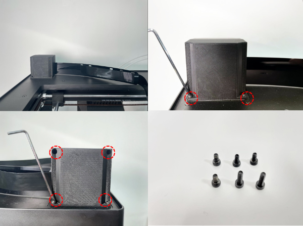
Figure 5 Remove the 6 screws on the front and back of the cover.
6. Remove the back cover. Remove 4 screws on the flat cable spacer. Press the buckle to pull the flat cable out of the socket.
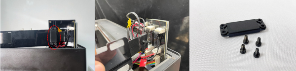
Figure 6 Remove the flat cable.
7. Remove the 5 connecting wires on the upper side of the extruder adapter board.
Note: Please label each wire according to the marks. Otherwise, you may feel confused about the position of each wire when reconnecting them.
①Magnetic Wire of Side Door(marked as SD)
②Magnetic Wire of Front Door(marked as FD)
③Connecting Wire of Right Filament Run-out Sensor(marked as MMDR)
④Connecting Wire of Left Filament Run-out Sensor(marked as MMDL)
⑤Magnetic Wire of Top Cover(marked as CDT)
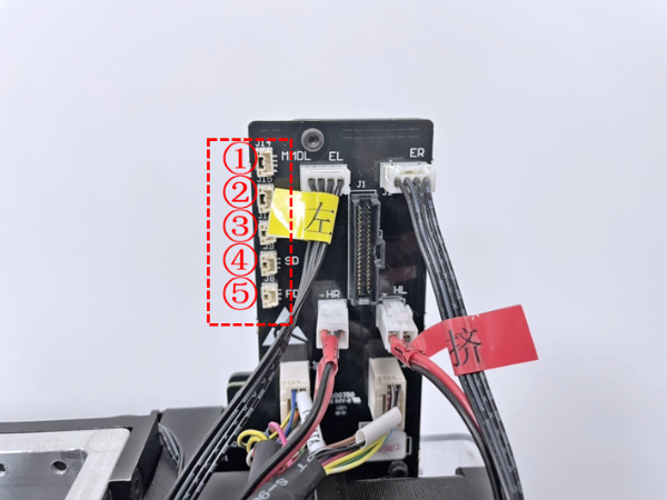
Figure 7 Remove 5 connecting wires on the upper side of the extruder adapter board.
8. Lift the top cover slightly, and then remove the top cover.
Note: When removing the top cover, be careful not to pull other cables on the extruder adapter board.
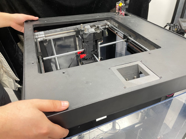
Figure 8 Remove the top cover.
1. Unplug all connecting cables on the old extruder adapter board.
Note: You can label the connecting wires according to the marks to avoid confusing them when connecting these cables later.

Figure 1 Unplug 6 cables on the extruder adapter board.
1. Prepare the new top cover.
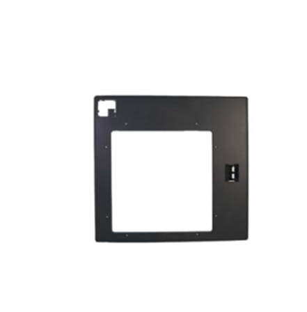
Figure 1 Prepare the new top cover.
2. Connect all the cables in the red area to the extruder adapter board.
Note: The previous task of marking each wire is helpful when inserting the cables back to the original position.
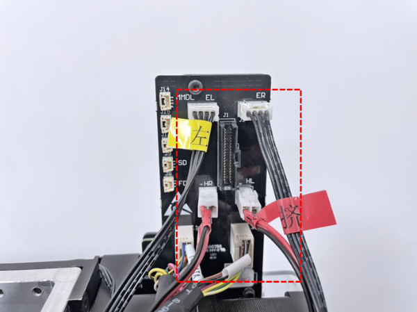
Figure 2 Connect all the cables.
3. Put the top cover through the extruder adapter board and put it back on the printer. Align the top cover with the printer body, and pass the cables through the hole.
Note: Do not press the top cover against other wires.

Figure 3 Put the top cover back on the printer.
4. Insert 8 long screws on the top cover into the screw holes. Then insert the 11 Phillips securing screws that fix the top cover around the printer body into the screw holes, and tighten all the screws at once.
Note: The long screws on the top cover need to be tightened with a 2.5mm hex wrench, and the screws around the body need to be tightened with a Phillips screwdriver.
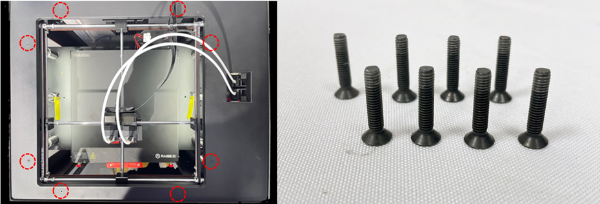
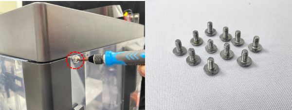
Figure 4 Tighten the fixing screws on the top cover and around the printer body.
5. Insert the 5 connecting wires back to the extruder adapter board in order. Insert the wires back to their position. Do not connect the wires to the incorrect position. This is when previous task of labeling wires is helpful.
①Connecting Wire of Left Filament Run-out Sensor(marked as MMDL)
②Connecting Wire of Right Filament Run-out Sensor(marked as MMDR)
③Magnetic Wire of Top Cover(marked as CDT)
④Magnetic Wire of Side Door(marked as SD)
⑤Magnetic Wire of Front Door(marked as FD)

Figure 5 Insert the 5 connecting wires back to the extruder adapter board in order.
6. Insert the flat cable to the socket. Then fix the front cover on the printer, and tighten the 2 securing screws.
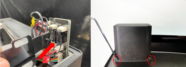
Figure 6 Insert the flat cable, then install the front cover to the printer.
7. Fix the flat cable on the front cover with the spacer, and tighten the 4 securing screws.
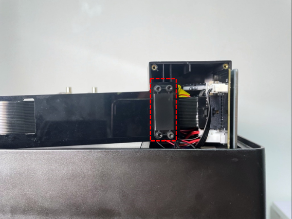
Figure 7 Fix the flat cable on the front cover with the spacer.
8. Reinstall the back cover, and tighten the 4 securing screws.
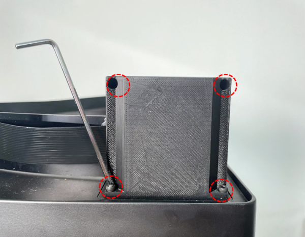
Figure 8 Reinstall the back cover, and then tighten the 4 securing screws.
1. Turn on the extruder and run a print test to check whether the printer is working properly. If you encounter any contact, please contact support support@raise3d.com for technical support.
[15.058-EN.1.0.20220513-Pro3 Series-How to Replace the Top Cover]
-END-
