
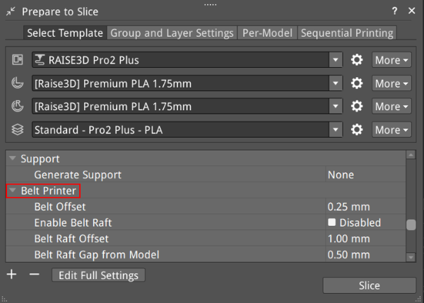
Figure 1: Belt Printer.
Belt Offset: Refers to the distance between the model and the conveyor belt.
Enable Belt Raft: Means ideaMaker will automatically generate a Raft to help a model stick to the printing surface. The Belt Raft is composed of a few layers placed on the printing surface before printing the model.
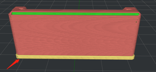
Figure 2: Enable Belt Raft.
Belt Raft Offset: Refers to the distance between the model and the expanded Raft area around the model.

Figure 3: Set Belt Raft Offset to 1mm.
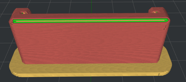
Figure 4: Set Belt Raft Offset to 5mm.
Belt Raft Gap from Model: Refers to the gap between the last layer of the Raft and the first layer of model.
Belt Raft Thickness: Refers to the thickness of the Raft.
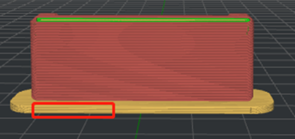
Figure 5: Set Belt Raft Thickness to 1.5mm.
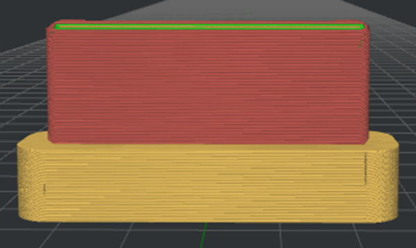
Figure 6: Set Belt Raft Thickness to 10mm.
Belt Raft Speed: Refers to the printing speed for the Raft.
Belt Raft Flowrate: Refers to the flow rate of printing the Raft.
Belt Raft Acceleration: Refers to the printing acceleration speed for the Raft.
Belt Raft Jerk: Refers to the printing jerk speed for the Raft.
Enable Belt Wall: The Belt Wall is the area of the model which touches the conveyor belt. ideaMaker will automatically apply the specified belt wall settings to the outer shells, which touches the conveyor belt to increase adhesion to the printing surface.
Belt Wall Minimal Length: Refers to the segment that will be printed with belt wall settings if the length of the segment is not shorter than the minimal length.
Belt Wall Speed: Refers to the printing speed for the wall.
Belt Wall Flowrate: Refers to the flow rate of printing the wall.
Place Seam on Belt Edge: With this function enabled, the starting point of the Outer Shell, Inner Shell, and Support Infill Outline will be placed at the center of the edges, touching the conveyor belt. If no starting point is found at the edges, ideaMaker will follow the strategy defined in the options Layer Start Point Type and Place Seam on.
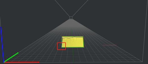
Figure 7: Disable Place Seam on Belt Edge.
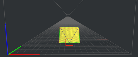
Figure 8: Enable Place Seam on Belt Edge.
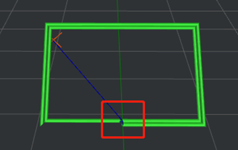
Figure 9: The Starting Point of the Inner Shell.
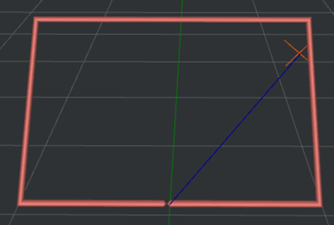
Figure 10: The Starting Point of the Outer Shell.
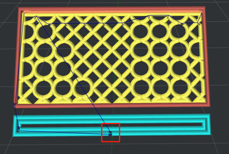
Figure 11: The Starting Point of the Support Infill Outline.
Notes:
1. This option only works for the belt printer and is disabled by default.
2. This option can be used when the Belt Printer function is enabled and can be found under Printer Settings.
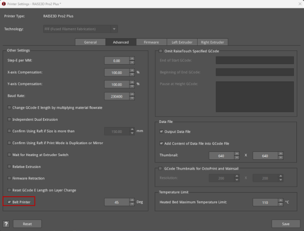
Figure 12: Belt Printer.
