
(1) General
Layer Height: The thickness of every single layer. It is also referred to as resolution.
First Layer Height: The thickness of the model’s first layer.
(2) Extrusion Width
First Layer Extrusion Width Percentage: The percentage of the first layer extrusion width. For example, if your extrusion width is 0.4mm and you set this value to 120%, the first layer extrusion width is 0.48mm.
First Layer Solid Fill Extrusion Width Percentage: The percentage of first layer’s solid fill extrusion width. For example, if your extrusion width is 0.4mm and you set this value to 120%, the first layer solid fill extrusion width is 0.48mm.
Outer Shell Extrusion Width Percentage: The percentage of the outer shell extrusion width. For example, if your extrusion width is 0.4mm and you set this value to 120%, the outer shell extrusion width will be 0.48mm.
Inner Shell Extrusion Width Percentage: The percentage of the inner shell extrusion width. For example, if your extrusion width is 0.4mm and you set this value to 120%, the inner shell extrusion width will be 0.48mm.
Infill Extrusion Width Percentage: The percentage of infill extrusion width. For example, if your extrusion width is 0.4mm and you set this value to 120%, the infill extrusion width is 0.48mm.
Base Solid Fill Extrusion Width Percentage: The percentage of base solid infill extrusion width. For example, if your extrusion width is 0.4mm and you set this value to 120%, the base solid infill extrusion width is 0.48mm.
Solid Fill Extrusion Width Percentage: The percentage of solid infill extrusion width. For example, if your extrusion width is 0.4mm and you set this value to 120%, the solid infill extrusion width is 0.48mm.
Top Surface Solid Fill Extrusion Width Percentage: The percentage of solid top surface layers extrusion width. For example, if your extrusion width is 0.4mm and you set this value to 120%, the solid top surface layers’ extrusion width is 0.48mm.
Bottom Surface Solid Fill Extrusion Width Percentage: The percentage of solid bottom surface layers extrusion width. For example, if your extrusion width is 0.4mm and you set this value to 120%, the solid bottom surface layers’ extrusion width is 0.48mm.
Support Extrusion Width Percentage: The percentage of the support extrusion width. For example, if your extrusion width is 0.4mm and you set this value to 120%, the support extrusion width will be 0.48mm.
(3) Dimensional Compensation
XY Size Compensation for Contours: The compensation for the measured error of contours, especially for the expanded or shrunken object. Positive values will increase the outline of the model and negative values will decrease the outline of the model.
XY Size Compensation for Holes: The compensation for the measured error of holes.
Positive values will decrease the holes of the model and negative values will increase the holes of the model.
(4) Elephant Foot Compensation
First Layer XY Size Compensation for Contours: The first layer’s compensation for the measured error of contours, especially for the expanded or shrunken object. Positive values will increase the contour of the model and negative values will decrease the contour of the model.
First Layer XY Size Compensation for Holes: The first layer’s compensation for the measured error of holes. Positive values will decrease the holes of the model and negative values will increase the holes of the model.
(5) Flowrate
First Layer Flowrate: Sets the flow rate at the first layer as a percentage of the filament flowrate. Flowrate refers to the amount of filament extruded by the extruder.
First Layer Solid Fill Flowrate: Sets the flow rate of solid fill at the first layer as a percentage of the filament flowrate. Flowrate refers to the amount of filament extruded by the extruder.
Outer Shell Flowrate: The flow rate when printing the outer shell structure, which is expressed as a percentage of filament flowrate.
Inner Shell Flowrate: The flow rate when printing the inner shell structure, which is expressed as a percentage of filament flowrate.
Infill Flowrate: The flow rate when printing the infill structure. Flowrate refers to the amount of filament extruded by the extruder. 100% is the default value.
Base Solid Fill Flowrate: The flow rate of the solid part at the bottom of the model.
Solid Fill Flowrate: The flow rate of the solid part for the model.
Narrow Solid Fill Flowrate: The flow rate of the narrow solid part for the model. ideaMaker will detect internal narrow solid fill regions when the setting of “Use concentric filling for narrow solid fill parts” is enabled.
Top Surface Solid Fill Flowrate: The flow rate when printing the surface solid part at the top of the model.
Narrow Top Surface Solid Fill Flowrate: The flow rate when printing the surface narrow solid part at the top of the model. The flow rate for printing narrow top surfaces is adjusted when the area or width of the region is smaller than a specified value. You can control which top surface regions are considered narrow by adjusting the Conditional Top Surface Pattern Type (Min Width) and Conditional Top Surface Pattern Type (Min Area) settings.
Bottom Surface Solid Fill Flowrate: The flow rate when printing the surface solid part at the bottom of the model.
(6) Shrinkage Compensation: The scaling factor is used for material shrinkage compensation. All models will be scaled along X/Y/Z according to the scaling factor to compensate.
Scale Factor X: Compensate for the shrinkage of the model on the X-axis, expressed as a percentage.
Scale Factor Y: Compensate for the shrinkage of the model on the Y-axis, expressed as a percentage.
Scale Factor Z: Compensate for the shrinkage of the model on the Z-axis, expressed as a percentage.
(7) Precise Z Height: Use this option to match the object’s height by adjusting the layer height of last few layers near the top of the model.
Precise Z Height Layers: The number of layers near the top that will have their layer height adjusted to match the object’s height. For example, the Z-axis height of the model is 10.15mm, the first layer’s thickness is 0.2mm, and each layer’s thickness is 0.2mm. If set Precise Z Height Layers to 10, the thickness of the 10 layers near the top after slicing will be changed from 0.2mm to 0.195mm. The final height after slicing is 0.2mm + 0.2mm x 40 layers + 0.195mm x 10 layers = 10.15mm.
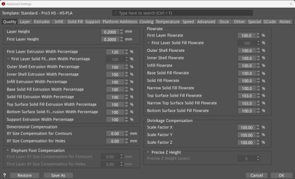
Figure 1: The Quality tab.
