


- Applications
- Support
- Support Center
- Download
Inquiry@raise3d.com
+1 888 963 9028
© 2019. All Rights Reserved. Raise 3D Technologies, Inc.

(1)Other:
Force Retraction On Layer Change refers that the retraction will automatically be triggered when the current layer print completes and the next layer starts.
Force Retraction Before Traveling to Outer Shell refers that the reaction will automatically be triggered before the extruder start move to outer shell.
Avoid Retraction Inside Model refers to disabling retraction when printing the inner structures of the model.
Enable Retraction at Bottom and Top of models refers that with this function enabled the retraction will be triggered at model’s top and bottom layers even if the retractions are disabled inside models.
Bottom Layers refers to the number of bottom solid layers in which retraction will be enabled.
Top Layers refers to the number of top solid layers in which retraction will be enabled.
(2)Travel:
Avoid Traveling Through Holes refers to the printer will pass around the hole parts automatically to avoid leaving strings inside the holes.
Maximum Travel Path Length refers that the extruder will move through the hole directly, if the travel path length of move around the hole is longer than the maximum value.
(3)Other:
Stop printing Wipe Wall and Wipe Tower if only one extrude is used in remaining task and the other extruder(s) will cooling down ideaMaker will detect how many extruders will be used in the remaining printing task, if it only uses one extruder, it will not print wipe wall and wipe tower any more, and it will stop heating the useless extruder.
(4)Wipe Wall:
Enable Wipe Wall means when printing a model with dual-extrusion, a nozzle will print a few extra shells around the model. This wipe wall will help to clean the nozzle while printing.
Wipe Wall Offset refers to the distance between the outline of the model and the wipe wall.
Wipe Wall Angle refers to the maximum allowed angle change which the wipe wall will generate (from 0 to 90).
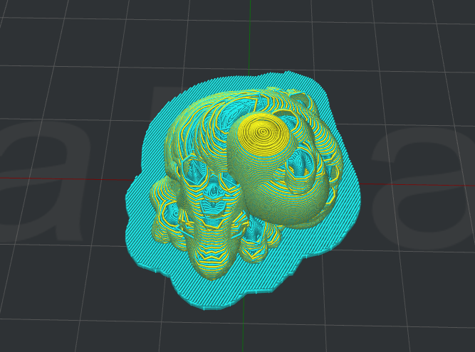
Figure 5.82: Set "Wipe Wall Angle" to be 90.
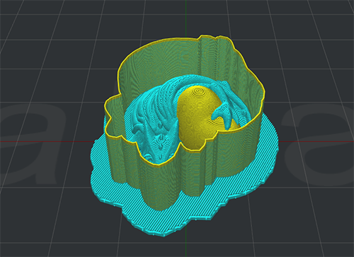
Figure 5.83: Set "Wipe Wall Angle" to be 0.
Wipe Wall Loop Lines refers to the quantity of the shells of wipe wall.
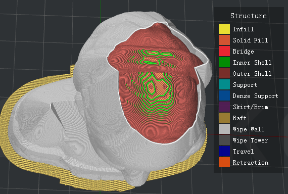
Figure 5.84: Set "Wipe Wall Loop Lines" to be one.
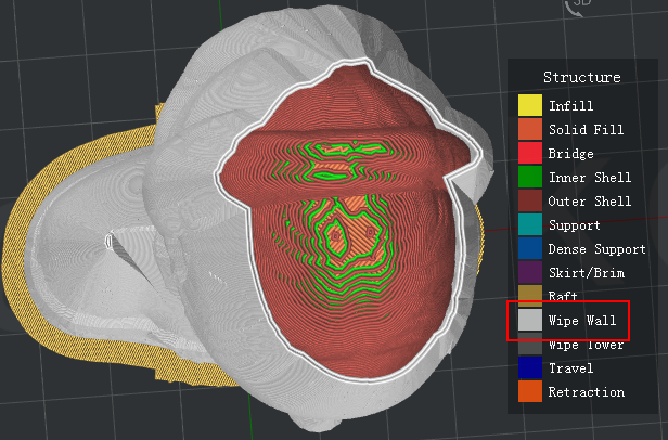
Figure 5.85: Set "Wipe Wall Loop Lines" to be two.
Wipe Wall Type refers to the shape of the wipe wall shells. The primary difference is the distance of model and wipe wall.
Contoured is the one which is closest to the origin model shape. Water fall is the type which will follow the origin shape, but a vertical drop if the lower structure is narrow that the above one. Vertical will find the widest part of the model and generate a vertical type wipe wall.
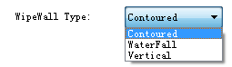
Figure 5.86: Three types of Wipe Wall.
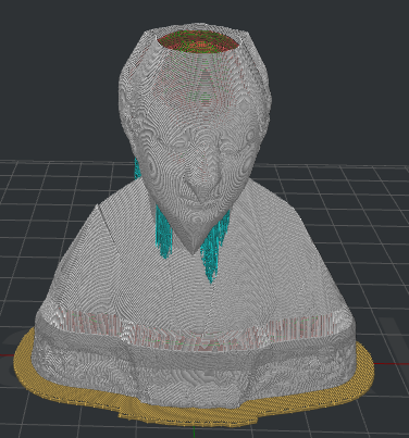
Figure 5.87: Set "Wipe Wall Type" to be "Contoured".
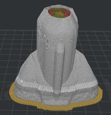
Figure 5.88: Set "Wipe Wall Type" to be "WaterFall".
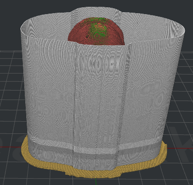
Figure 5.89: Set "Wipe Wall Type" to be "Vertical".
Wipe Wall Speed refers to the printing speed for wipe wall.
(5)Wipe Tower:
Wipe Tower refers to a block created outside of the model which is used for wiping the nozzle which is going to start print.
Wipe Tower Width refers to width of the wipe tower.
Wipe Tower Infill Ratio refers to the density of wipe tower structure.
Wipe Tower Speed refers to the printing speed for wipe tower.
Placed at the Fixed Position of the plate refers to with this function enabled Wipe Tower’s position would be fixed as Figure 5. 90.
Wipe Tower Fixed Position X refers to the position in X direction.
Wipe Tower Fixed Position Y refers to the position in Y direction as Figure 5.91.
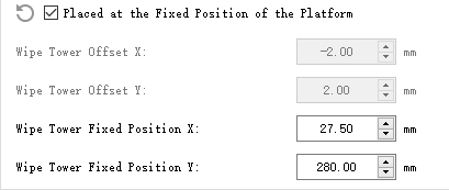
Figure 5.90: Wipe Tower Fixed Position.
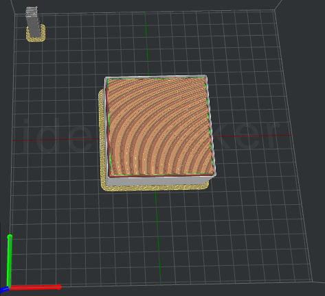
Figure 5.91: Enable the function of Placed at the Fixed of the Platform.
Wipe Tower Offset X refers to the distance between Wipe Tower and the model in the direction of X.
Wipe Tower Offset Y refers to the distance between Wipe Tower and the model in the direction of Y.
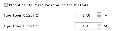
Figure 5.92: Wipe Tower X/Y offset.
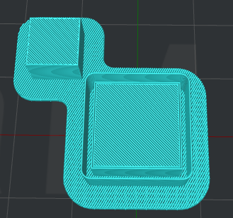
Figure 5.93: Wipe Tower.
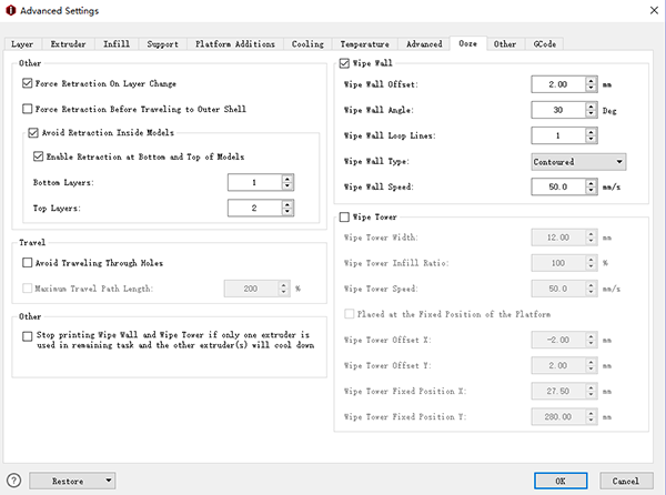
Figure 5.94: The Ooze tab.
-END-
Inquiry@raise3d.com
+1 888 963 9028