
(1) Merge Open Segments of Model Parts: Merges the non-closed polygons in the model parts.
Merge Internal Overlapping Parts: Merges the overlapping parts inside the model.
Print Non-Manifold Edges: With this function enabled, ideaMaker will keep the model’s non-manifold edges during slicing, and it will be extruded as single extruding lines.
(2) Check Thin Wall (Single Extrusion Width): Checks if the width of the model parts is less than the defined thin wall width and extrudes as a single extrusion width.
Minimal Extrusion Width Percentage: The minimum percentage of extrusion width.
Maximum Extrusion Width Percentage: The maximum percentage of extrusion width.
For Example, if the extrusion width is 0.4mm and you set Minimal Extrusion Width Percentage to 25%, the minimal thin wall will be 0.1mm. If you set Maximum Extrusion Width Percentage to 200%, the maximum thin wall will be 0.8mm.
If the thin wall’s width is less than 0.1mm, it will print nothing as its width is less than the minimal extrusion width. If the thin wall’s width is larger than 0.1mm, but less than 0.8mm, the system will extrude one single extrusion path instead and the width of the single path will be adapted to the size of the space dynamically.
(3) Fill Gaps in Shells: With this function enabled, there will be no gaps between shells, as shown in Figure 1 and 2.
Fill Gaps only at Top and Bottom Surfaces: With this function enabled, filling gaps are only used on the outer surfaces of the top and bottom of the model, and other inner solid fill areas will not generate additional gap fills. Enabling this function for some models or materials can reduce the printing time.
Allow Filling Gaps using Single Extrusion Filling: With this function enabled, the gap will be filled by a single extrusion filling.
Minimal Single Extrusion Width Percentage: The minimum percentage of single extrusion width.
Maximum Single Extrusion Width Percentage: The maximum percentage of single extrusion width.
For example, if the extrusion width is 0.4mm and you set the Minimal Singe Extrusion Width Percentage to 50%, the single extrusion width is 0.2mm. If you set the Maximum Singe Extrusion Width Percentage to 200%, the maximum single extrusion width is 0.8mm. If the gap is less than 0.2mm, it will not be filled. If the gap is larger than 0.2mm and less than 0.8mm, it will be printed by a single extrusion filling. And the width of the single extrusion filling will be adapted to the size of the space dynamically.
Single Extrusion Filling Compensation: If the extrusion width of the single extrusion filling is too small, the nozzle will not extrude such a thin line and leave an unfilled gap. This function will increase the flow rate to make the actual extrusion width not lower than the specified value instead of extruding nothing.
Notes:
1. This function will change the E value of the GCode commands, but it will not affect the GCode preview.
2. Extruder will not extrude any filament if the extruding amount is too small.
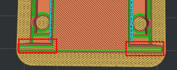
Figure 1: Enable "Fill Gaps in Shells".
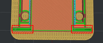
Figure 2: Disable "Fill Gaps in Shells".
Gap Filling Minimal Length: Removes the gap filling which is shorter than the defined value.
(4) Overhang Shells Detection: With this function enabled, the system will detect the structure of overhang shells automatically and modify the overhang shells’ printing speed and flowrate.
Overhang Shells Angle: If the Overhang Angles on the model are larger than the Overhang Shells Angle, shells on those parts of the model will be printed based on the settings for Overhang Shells, including printing speed, flowrate and fan speed. The default Overhang Shells Angle is 30 degrees.
Overhang Shells Flowrate: The flow rate on the overhang shells as a percentage of the filament flowrate.
Enable Overhang Shells Fan Speed: Allows the overhang shells’ cooling fan speed to be modified.
(5) Global Offset: You can apply X/Y/Z offset to all coordinates in the GCodes.
You can set X-Offset, Y-Offset and Z-Offset separately.
(6) Pause at Height: The printer will automatically suspend a print job at the defined height. You can do several operations such as changing filament, and then resume printing. You can define the height by clicking the Add button, and delete the defined height by selecting the value in the right box and clicking the Remove button.
Note: This height doesn’t include Raft. For Raise3D printers, ideaMaker will output the M2000 command to tell the printer to pause at the specified position. For the third-party printers, custom commands can be modified in Printer Settings > Advanced > Pause at Height GCode.
(7) Enable Bridging Detection: With this function enabled, the system will detect a bridge structure automatically.
Extrusion Width Percentage: The percentage of bridging extrusion width. For Example, if the extrusion width is 0.4 mm and you set this value to 120%, the bridging structures extrusion width will be 0.48 mm.
Enable Bridging Fan Speed: With this function enabled, the fan speed of bridging can be modified.
Enable Fixed Bridging Angle: With this function enabled, the fill lines’ angle of bridging structures will be fixed as the value you set.
Minimal Allowed Bridging Area: If the bridging area is less than the value you set, ideaMaker will regard it as a solid fill instead of a bridging structure.
Bridging Flowrate: The flow rate for printing the bridging structure.
Maximum Supported Area Percentage: If the supported area is larger than the percentage of bridging area, the bridging detection will be disabled in these regions. Setting the option to 0 will disable bridging detection on all support regions.
Apply Bridging Settings to Shells: With this function enabled, the bridging shells’ speed and flowrate can be modified.
Bridging Shells Flowrate: The flow rate at the bridging shells as a percentage of filament flowrate. This function will take effect only when Apply Bridging Setting to Shells is enabled.
(8) Small Features
Parts detected as Small Features can be printed at different speeds and will fill densities to enhance print results. Common small features such as pins, which require slower speed to print, need a lot of time to cool the filament. Also, higher fill densities can increase the strength of the pins.
When the diameter of a selected area is lower than the set value, or when the diameter of holes on shells is smaller than the set value, these sections will be printed out with the settings of Small Features, which require a lower printing speed and an increased infill density.
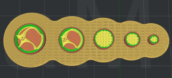
Figure 3: The difference between Small Features and Non-Small Features during printing.
Small Features Diameter: The regions where the detected small feature diameter is smaller than the defined value will be printed with Small Features settings.
Small Features Holes Diameter: The shells where the detected holes’ diameter is smaller than the defined value will be printed with Small Features settings.
Small Features Speed Multiplier: The printing speed percentage for the detected small feature areas.
For example, if the Small Features Speed Multiplier is 50%, and you set the Infill Speed to 80mm/s, the small features’ infill regions will be printed at a speed of 40mm/s.
Small Features Infill Density: With this function enabled, the infill density of detected small features area will be set as the defined value.
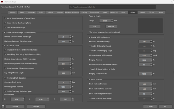
Figure 4: The Other tab.
