
(1) Lateral Surface Texture: The textures can be added to the selected model to overlay the model. The Texture function only allows you to overlay the texture on the side of model. The top surface of the model will not be covered with texture.
Texture Lighter Color Up: The lighter color of the texture will be printed as a new boundary, which will be offset from the original surface’s boundary.
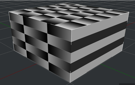
Figure 1: A 3D model with texture.
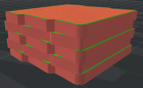
Figure 2: The “Texture Lighter Color Up” is enabled.
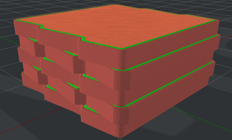
Figure 3: The “Texture Lighter Color Up” is disabled.
Texture Color Normalized: The color in the texture will be normalized when it is used for calculating Lateral Surface Texture XY Offset.
For example, the maximum color pixel is 200, and the minimum color pixel is 50. With this function enabled, the color will be normalized to be 0-255.
Texture XY Offset: The maximum offset distance from the texture to the original model’s surface in the X/Y direction. A negative offset value will push the surface boundary into the inner structures.
For example, if you set Texture XY Offset to 1, a color pixel of 255 will protrude outwards 1mm. If you set Texture XY Offset to -1, a color pixel of 255 will protrude inwards 1mm. If you set Texture XY Offset to 0, the texture will be ignored.
Texture Resolution: The sampling distance when picking up the color in the texture.
Texture Outside Only: With this function enabled, the texture will only cover the outside of the model, and will not be applied to inner holes.
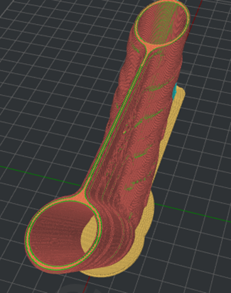
Figure 4: Texture will not be applied to the holes in the model.
(2) Belt Printer
Belt Offset: The distance between the model and the conveyor belt.
Place Seam on Belt Edge: The start point of the Outer Shell, Inner Shell, and Support Infill Outline will be placed at the center of the edges that touch the conveyor belt. If no point is found at the edges, ideaMaker will follow the settings of Layer Start Point Type and Seam Hiding.
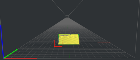
Figure 5: The "Place Seam on Belt Edge" is disabled.
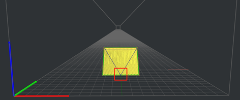
Figure 6: The “Place Seam on Belt Edge” is enabled.
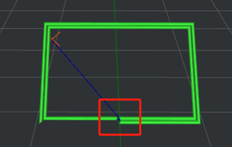
Figure 7: The Start Point of the Inner Shell.
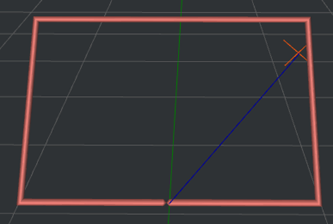
Figure 8: The Start Point of the Outer Shell.
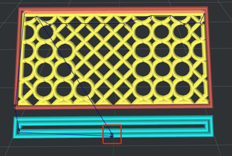
Figure 9: The Start Point of the Support Infill Outline.
Notes:
1. It only works for the belt printer and this option is disabled by default.
2. It can be used only when the Belt Printer function is enabled, and this function can be found in the Printer Settings panel.
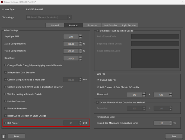
Figure 10: The Belt Printer function in the Printer Settings panel.
(3) Belt Raft: With this function enabled, ideaMaker will automatically generate a Raft to help the model stick to the printing surface. The Belt Raft is composed of a few layers placed on the printing surface before printing the model.
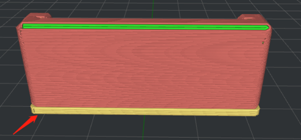
Figure 11: Enable Belt Raft.
Belt Raft Offset: The distance between the model and the extra Raft area around the model.

Figure 12: Set the "Belt Raft Offset" to 1mm.
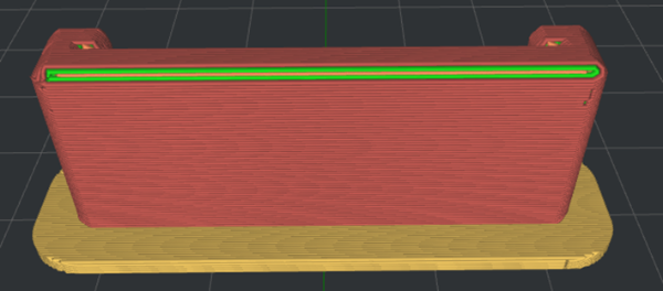
Figure 13: Set the "Belt Raft Offset" to 5mm.
Belt Raft Gap from Model: The gap between the last layer of the Raft and the first layer of model.
Belt Raft Thickness: The thickness of the Raft.
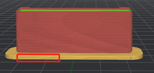
Figure 14: Set the "Belt Raft Thickness" to 1.5mm.
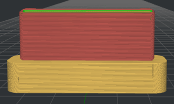
Figure 15: Set the "Belt Raft Thickness" to 10mm.
Belt Raft Speed: The printing speed for the Raft.
Belt Raft Flowrate: The flow rate for printing the Raft.
Belt Raft Acceleration: The printing acceleration speed for the Raft.
Belt Raft Jerk: The printing jerk speed of the Raft.
(4) Belt Wall: Belt Wall is the area in the model that touches the conveyor belt. With this function enabled, ideaMaker automatically applies the specified Belt Wall settings to the outer shells, touching the conveyor belt to increase adhesion to the printing surface.
Belt Wall Minimal Length: The segment will be printed with Belt Wall settings if the length of the segment is not shorter than the minimum length.
Belt Wall Speed: The printing speed for the outer shells which are touching the conveyor belt.
Belt Wall Flowrate: The flow rate for printing the outer shells which are touching the conveyor belt.
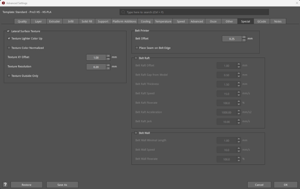
Figure 16: The Special tab.
