
Note: If you have set the Extruder Count to be 2, the Extruder tab will show Left Extruder and Right Extruder. If you have set the Extruder Count to be 1, the Extruder tab will show Primary Extruder only. And we set the primary extruder as left extruder by default.
If the right extruder is not enabled it will use settings for the left such as Extrusion Width, Enable Retraction, Retraction speed, Retract Material Amount, Minimal Travel of Retraction, Minimal Amount of Retraction, Extra Restart Amount, Restart Speed and Z hop at Retraction.
Left Extruder:
(1) General
Extrusion Width refers to the width of extruded line. The default extrusion width will be the same as diameter of the original 0.4mm nozzle. If you have changed your nozzle to be other size in Printer Settings, please also remember to edit Extrusion width.
(2) Retraction
Enable Retraction refers to enabling filament retraction to prevent stringing.
Retraction speed refers to the extruder speed for the retraction. A higher retraction speed works better. But it can lead to filament grinding when the speed is too high.
Retract Material Amount refers to the amount of retraction. Setting the value to be 0 means that there is no retraction at all.
Minimal Travel of Retraction refers to the minimum distance of extruder motor reserves that defines if the filament needs to be retracted. Set this item to make sure you do not get a lot of retractions in a small area.
Minimal Amount of Retraction refers to the minimal amount of extrusion that defines if the filament needs to be retracted. If the amount of extrusion for printing is less than the minimal amount of retraction, the retraction will be ignored by system automatically. This avoids retracting a lot on the same piece of filament which flattens the filament and causes grinding issues.
Extra Restart Amount refers to the amount of extrusion compensation after the retraction.
Restart Speed refers to the extruder speed when the filament is extruded out after the retraction.
Avoid Unnecessary Retraction in Support with this function enabled, extruder will reduce unnecessary retractions when printing support fill lines.
Note:
1. This function can avoid filament grinding and reduce printing time. But it will make oozing between supports.
2. If travel moves across models or holes when printing supports, retraction will be enabled still to avoid collision with printed parts.
Z Hop at Retraction the nozzle will lift from the surface of the model during retraction. Normally retraction is set before long-way movement which normally has faster moving speed than normal printing. Z Hop can reduce the effects of nozzle scratching during fast move.
Z Hop performed refers to the selected structures will be performed Z Hop.
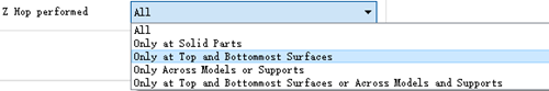
Figure 1: Select when the Z Hop is performed
All with this option selected, Z Hop will be performed anywhere during retraction.
Only at Solid Parts with this option selected, Z Hop will be performed at top and bottom solid fill layers only.
Only at Top and Bottommost Surfaces with this option selected, Z Hop will be performed at top and bottommost surface solid fill layers only and the bottommost surfaces are not floated in the air.
Only Across Models or Supports with this option selected, Z Hop will be performed only for avoiding collision when moving from the model to the supports or from the supports to the model.
Only at Top and Bottommost Surface or Across Models and Supports with this option selected, Z Hop will be performed when printing from the top and bottommost surface, or across from the model to the supports and from the supports to the model only.
(3) Coasting
Coasting Distance: with this function enabled the last part of the extrusion path will be replaced with a travel path only with no extrusion as Figure 2. The distance of the extrusion path’s last part is the Coasting Distance.
Enabling the function of Coasting Distance can decrease the filament leaking when nozzle travels from one point to another point.
Apply Coasting on Gird Infill and Lines Solid Fill refers that with this function enabled the last part of the infill extrusion path will be replaced with a travel path only with no extrusion as Figure 4.
Note: Please don’t set the Coasting Distance too large. Or it may cause gaps between layers.

Figure 2: Coasting Distance set to be 2mm.

Figure 3: Set Coasting Distance to be 0.

Figure 4: "Apply Coasting on Gird Pattern Infill and Lines Pattern Solid Fill" enabled.
(4) Wipe
Outer Shell Wipe Distance refers to the nozzle wipe distance at the end of the outer shell as shown in Figure 5.
Outer Shell Wipe Speed refers to the printer head movement speed at the end of the outer shell.
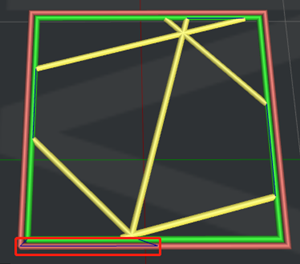
Figure 5: Outer Shell Wipe Distance set to 10mm.
Wipe Nozzle for Support refers to the nozzle wipe distance at the end of the support as shown in Figure 6.

Figure 6: " Wipe Nozzle for Support" set to 10mm.
Wipe Nozzle for Infill refers to the nozzle wipe distance at the end of the infill as shown in Figure 7.

Figure 7: " Wipe Nozzle for Infill" set to 5mm.
Wipe Nozzle for Solid Fill refers to the nozzle wipe distance at the end of the solid infill as shown in Figure 8.

Figure 8: " Wipe Nozzle for Solid Infill" set to 10mm.
Wipe Nozzle for Thin Wall refers to the nozzle wipe distance at the end of the Thin Wall.
(5) Extruder Switch Ooze Control
Extruder Switch Ooze Control refers to the retraction settings for extruder when one nozzle completes printing of one layer and the other nozzle starts printing.
Retraction Speed of Extruder-Switch refers to the speed of retraction when extruder switch.
Retraction Amount of Extruder-switch refers to the amount of filament retraction for an extruder change. 0 refers to no retraction at all.
Restart Speed of Extruder-switch refers to the extrusion speed after the retraction for an extruder change.
Extra Restart Amount of extruder-switch refers to the amount of additional filament compensation after the retraction for an extruder change.

Figure 9: The Extruder tab.
Right Extruder:
Enable Right Extruder Configuration refers to enabling Right Extruder’s Configuration function the below settings will be activated such as Retraction. If not enabled, the right extruder will continue to use the settings of left extruder.
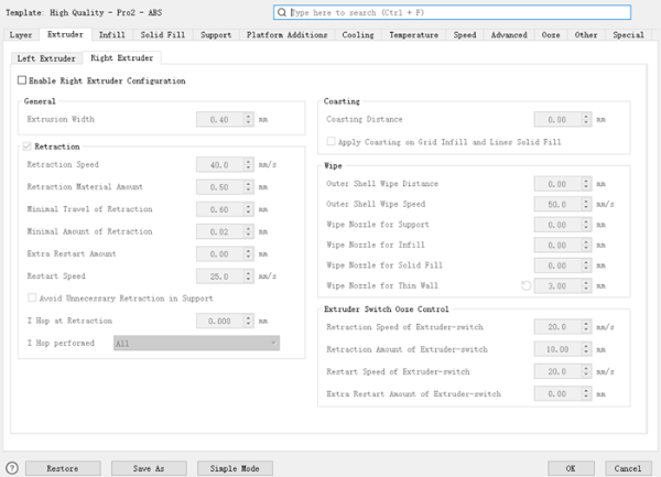
Figure 10: The Right Extruder Tab.
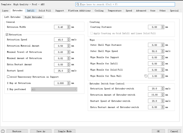
Figure 11: The Left Extruder Tab.
-END-
