
Shell: The number of loops for the models’ walls.
Maximum Shells Overlap Percentage: The max percentage of overlap between shells. When the overlap percentage of the lines from one single shell loop is larger than the set value, the shell will be replaced with a solid fill structure.
Print Shells in Optimal Order: With this function enabled, the shells will be printed with an optimized order that will reduce the travel paths and retractions.
First Layer Solid Fill Pattern Type: The solid fill pattern for the model’s first layer, including Lines, Rectilinear and Concentric.
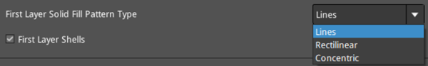
Figure 1: Select a "First Layer Solid Fill Pattern Type" depending on the model type.
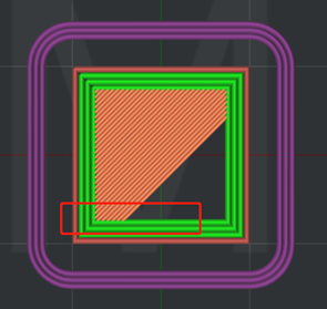
Figure 2: Set "First Layer Solid Fill Pattern Type" to "Lines".
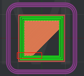
Figure 3: Set "First Layer Solid Fill Pattern Type" to "Rectilinear".
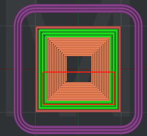
Figure 4: Set "First Layer Solid Fill Pattern Type" to "Concentric".
First Layer Shells: The number of loops for the models’ first layer wall.
Shells Direction List:
Orientation: CCW represents counterclockwise printing, and CW represents clockwise printing. Click Add to add a printing direction to the list and click Delete to remove the selected direction from the list.
If CCW, CCW and CW are added to the Shells Direction List, as shown in Figure 5, the first and second layers will be printed in a counterclockwise direction and the third layer will be printed in a clockwise direction; Then the fourth and fifth layers will also be printed in a counterclockwise direction and the sixth layer will also be printed in a clockwise direction, and so on until printing is complete. If only CCW and CW are added to the list, the layers will be printed alternately in a counterclockwise and clockwise direction until printing is completed.
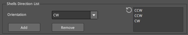
Figure 5: The Shells Direction List.
Scarf Joint: Apply scarf joints to the shell loops to reduce the visibility of the seams.
Scarf Joint Type: The usage type of scarf joints. None indicates not applying scarf joints at all; Contour Only indicates only applying scarf joints to the contour parts of the model; Contour and Hole indicates applying scarf joints to both the contour and hole parts of the model. Note: The scarf joint is only applicable to the arc parts of the model and not suitable for corners, overhanging surfaces, or bridge structures.
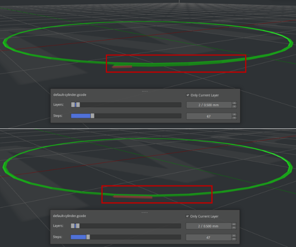
Figure 6: Slicing comparison between the joints with and without Scarf Joint enabled. (enabled for the first screenshot, and disabled for the second screenshot)
Conditional Scarf Joint: With this function enabled, the Scarf Joint Angle Threshold will be activated, and the scarf joints will not be applied to the set sharp corners. With this function disabled, scarf joints will apply to the shells regardless of the sharp corners.
Scarf Joint Angle Threshold: The angle threshold of the sharp corners in the shells. When the angle is less than this threshold, it is considered a sharp corner, and the scarf joints will not apply to this sharp corner.
Scarf joints around entire shell: With this function enabled, the scarf joints will be extended to cover the entire length of the shells, and the Scarf Joint Length will be invalid.
Scarf Joint Length: The length of a scarf joint.
Scarf Joint Steps: The minimum number of segments contained in a scarf joint.
Scarf Joint Start Height Ratio: The scarf joint begins at a specified height. The start height = this start height ratio x the current layer’s height.
Scarf Joint for Inner Shells: With this function enabled, the scarf joints will also apply to the inner shells.
Scarf Joint Speed Multiplier: Sets the printing speed for the scarf joints. The scarf joint speed for the outer shell = this speed multiplier x outer shell speed. The scarf joint speed for the inner shell = this speed multiplier x inner shell speed
Note: The first layer of the model is forced to disable the Scarf Joint.
Spiral Vase Mode: Means that the model will be printed out to be single outline corkscrew vase structure with no retraction. This mode will transfer the model to vase-like structure with only outer shell, no infill and open top surface. The Z-axis will spiral upwards slowly.
Spiral Vase Mode Path Interpolation: With this function enabled, under Spiral Vase Mode, if there is a large gap between the Upper and Lower layers in XY direction, ideaMaker will add an interpolation to evenly transition to the next layer. If it is disabled, ideaMaker will keep the original structure for printing, it may cause overhang or gap between layers.
Single Shell Surface Mode: With this function enabled, the model will print one single shell only, with no infill, no top or bottom solid fill, as shown in Figure 7. This function is suitable for non-manifold models, such as airfoils, etc.
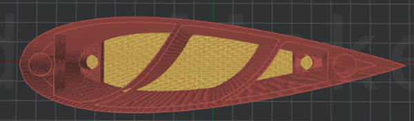
Figure 7: The "Single Shells Surface Mode" is enabled.
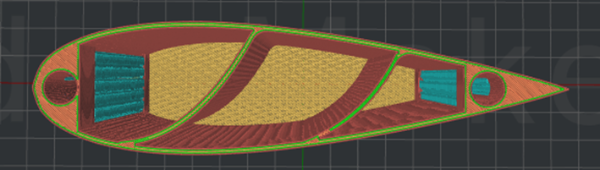
Figure 8: The "Single Shells Surface Mode" is disabled.
Shell and Infill Order: With this function enabled, the printing order of Inner Shell, Outer Shell and Infill can be customized, as shown in Figure 9.
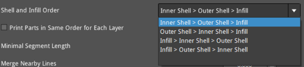
Figure 9: Four options of Shell and Infill Order.
Print Parts in Same Order for Each Layer: Refers that the models will be printed under a specific order in each layer. For a single model, the printing orders for each structure in each layer are the same, as shown in Figure 10. For multiple models, the printing orders for each layer of the models are the same and the orders depend on models’ importing order, as shown in Figure 11.
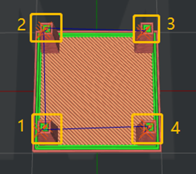
Figure 10: A single model.

Figure 11: Multiple models.
Minimal Segment Length: The minimal length of extruded line segment. The Minimal Segment Length is to avoid creating extremely small extruded line segments that could affect the printing result.
Merge Nearby Lines: If the distance of two nearby lines is less than the value you set, these two lines will be merged.
Minimal Part Size: The percentage of first layer extrusion width. For example, if your extrusion width is 0.4mm and you set this value to 80%, the minimal part size is (0.4mm x 80%) x (0.4mm x 80%) = 0.1024mm², and ideaMaker will automatically remove the structure less than 0.1024mm².
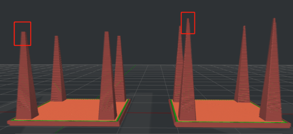
Figure 12: The "Minimum Part Size" is set to 100% (left) and 30% (right) respectively.
Only one shell on top surfaces: With this function enabled, keep only one shell on the top surfaces of the models to optimize the appearance of the models’ top surfaces.
Conditional One Shell Top Surface (Min Width): With Only one shell on top surfaces enabled, if the width of the top surface is more than this value, only one shell will be used when printing the top surface of the model; If the width of the top surface is less than this specified value, the top surface will not be printed with only one shell, but will be printed based on the set value of Shells. (The default value for Shells is 2.)
Conditional One Shell Top Surface (Min Area): With Only one shell on top surfaces enabled, if the area of the top surface is more than this value, only one shell will be used when printing the top surface of the model; If the area of the top surface is less than this specified value, the top surface will not be printed with only one shell, but will be printed based on the set value of Shells. (The default value for Shells is 2.)
Layer Start Point: The position where the nozzle starts moving at the beginning of each layer.
Layer Start Point Type: The type of position where the nozzle starts moving on each layer.
ØNearest: Placed at the nearest position to the last position to save movement time.
Ø Fixed: Placed as close as possible to a specified position. When you choose Fixed, you can set the Fixed Layer Start Point X/Y to specify the position. ideaMaker will set the closest position based on the position value you set.
Ø Random: Placed randomly over the model.
Ø Auto: Placed at a convex corner or reflex corner based on the Place Seam on option. ideaMaker will choose a fixed position if there is neither the convex corner nor the reflex corner found.
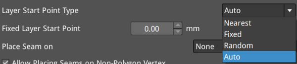
Figure 13: Four types for the Layer Start Point.
Fixed Layer Start Point: The X and Y positions of the layer start point.
Notes:
1. When the Build Plate Shape is Rectangular, Fixed Layer Start Point x=0 and y=0 refers to the bottom left corner of the platform.
2. When the Build Plate Shape is Elliptical, Fixed Layer Start Point x=0 and y=0 refers to the central point of the platform.
Place Seam on: Places the seam on the specified corner of the shells. When the Layer Start Point Type is Nearest or Auto, this function will be activated. There are four types in all: None, Reflex or Convex Corner, Reflex Corner, Convex Corner,
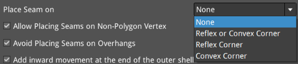
Figure 14: Four types for Place Seam on.
Allow Placing Seams on Non-Polygon Vertex: By default, ideaMaker selects vertices on the polygon of each layer’s structure as seams. However, this can sometimes lead to misaligned seams. With this function enabled, ideaMaker will calculate whether to select non-polygon vertices as seams or not. This allows for more precise alignment of the start points of most seams, improving the accuracy of the seams and overall visual effect. The start points are shown in white in the following figures.
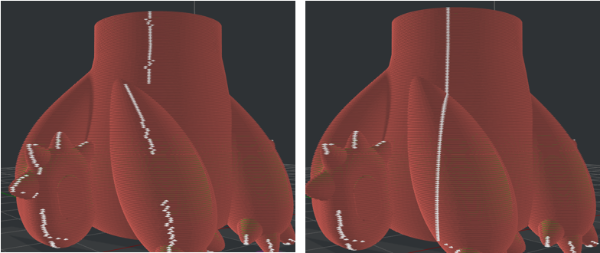
Figure 15: The comparison between disabled Allow Placing Seams on Non-Polygon Vertex (left) and enabled Allow Placing Seams on Non-Polygon Vertex (right).
Avoid Placing Seams on Overhangs: With this function enabled, ideaMaker will place seams of each layer away from the overhangs to avoid curling and wrapping at the edges. This function is enabled by default.
Add inward movement at the end of the outer shell: With this function enabled, adds an inward movement after the end of the outer shell loops to reduce the visibility of the seams.
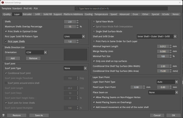
Figure 16: The Layer tab.
