
(1) Infill
Infill Extruder: The extruder which will be used to print infill. If you have set the number of extruders to 1, it will only show Primary Extruder; If you have set the number of extruders to 2, it will show three options: All Extruder, Left Extruder and Right Extruder. The All Extruder refers to the extruders selected to print the model.
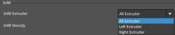
Figure 1: Select an Infill Extruder for your model.
Infill Density: The density of the infill inside the model. The more infill the model has, the more solid the model will be.
Infill Overlap: The percentage of overlap between the infill and the shell.
Infill Patter Type: Selects the infill pattern for the interior of the model.

Figure 2: Select an "Infill Pattern Type" depending on the model type.
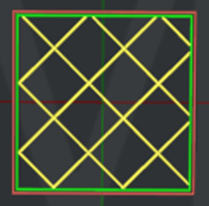
Figure 3: The "Infill Pattern Type" is set to "Grid".
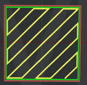
Figure 4: The "Infill Pattern Type" is set to "Rectilinear".

Figure 5: The "Infill Pattern Type" is set to "Honeycomb".
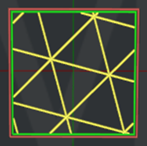
Figure 6: The "Infill Pattern Type" is set to "Triangles".
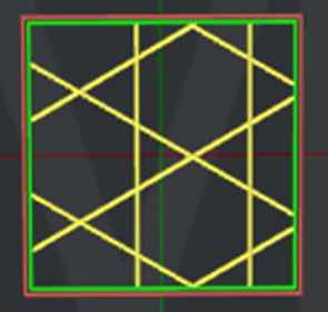
Figure 7: The "Infill Pattern Type" is set to "Cubic".
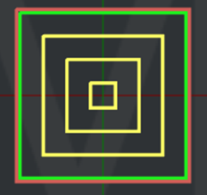
Figure 8: The "Infill Pattern Type" is set to "Concentric".
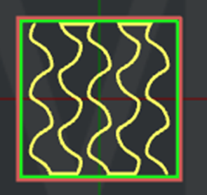
Figure 9: The “Infill Pattern Type" is set to "Gyroid".
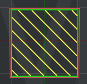
Figure 10: The "Infill Pattern Type" is set to "Lines".
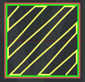
Figure 11: The "Infill Pattern Type" is set to "Symmetric Wavy Curve".
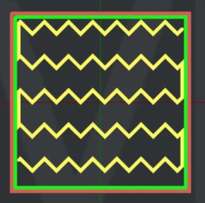
Figure 12: The "Infill Pattern Type" is set to "Wavy Lines".

Figure 13: The "Infill Pattern Type" is set to "Cross Hatch".

Figure 14: The "Infill Pattern Type" is set to “new pattern-0”.
Fill Gaps in 100% Concentric Infill: With this function enabled, ideaMaker will fill small gaps with solid fill pattern or single extrusions if the Infill Pattern Type is Concentric and infill density is 100%.
Connect Infill Lines Endpoints: With this function enabled, the endpoints of infill lines will be connected if the Infill Pattern Type is Grid, Cubic, Triangles or Lines.
Use Lines Pattern in Hight Density Grid Infill Pattern: With this function enabled, when using the grid infill pattern and infill density is greater than 25%, ideaMaker will change the infill pattern to Lines automatically.
Infill Offset X: With this function enabled, the slicer will apply X offset to the infill structure.
Infill Offset Y: With this function enabled, the slicer will apply Y offset to the infill structure.
Combine Infill Layers: With this function enabled, multiple layers of the infill structure will be combined and printed with a greater layer thickness to reduce printing time. For example, if you set Combine Infill Layers to 5, the first four layers will not print infill, and then the fifth layer will print an infill structure with greater layer thickness.
Infill Outline Shells: This refers to the infill outline shells around the infill structures created to improve the adhesion of infill structures.With this feature enabled, the printer will print a few loops around the infill structures to improve the adhesion of infill structures. Especially when the model has been set to use multiple infill patterns in one print, this function can improve the adhesion among different infill patterns.
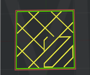
Figure 15: Infill Outline Shells is disabled.
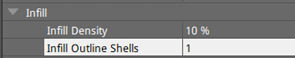

Figure 16: Infill Outline Shells is enabled.
Fill Gaps in Infill Outline Shells: With this function enabled, ideaMaker will fill small gaps in infill outline shells with solid fill pattern or single extrusions.
Print Solid Fill in 100% Infill: With this function enabled, the infill regions will be printed as solid fill with solid fill settings if the Infill Density is 100%.
Infill Minimal Width: With this function enabled, ideaMaker will ignore the infill regions with a width smaller than the defined value. For example, if you have set the Infill Minimal Width to 1mm, the infill will be ignored if the infill region’s width is smaller than 1mm. Setting the value to 0 will disable this function.
Infill Minimal Area: With this function enabled, ideaMaker will ignore the infill regions with an area smaller than the defined value.
(2) Adaptive Infill
Adaptive Infill: With this function enabled, ideaMaker will generate denser infill near the model’s top solid layers where it would otherwise make sparse fills.Note: Infill Ratio in Per-layer settings and Infill Ratio in modifier settings will be ignored if adaptive infill is enabled.
Adaptive Infill Reduction Count: The number of reductions for reducing the density of infill structure.
Infill Ratio Range: The minimum and maximum range of infill ratio.
Adaptive Infill Layers: The number of layers near the top solid layers where adaptive infill will be applied.
Adaptive Infill Inner Horizontal Expansion: With this function enabled, the adaptive infill structure would be expanded in the X/Y direction to avoid narrow infill regions.
Adaptive Infill Minimal Width: The minimal allowed width for adaptive infill regions. It will replace the narrow adaptive infill regions which are smaller than the value with other regions which have different density.
(3) Infill Angle
Infill Angle: You can define the direction of the infill structure in each layer. If you add 30º, 60º and 90º in the Angle box, the angle of the first layer of infill structure will be 30º, the second layer will be 60º, and the third layer will be 90º. The fourth layer will be back to 30º, and the angle of the following layers will change accordingly.
Angle: The directional angle of infill structure.
Add Infill Angle: Add an angle with the value defined by the user in the Angle box above.
Remove Infill Angle: Removes the angle with the value defined by the user in the Angle box above.
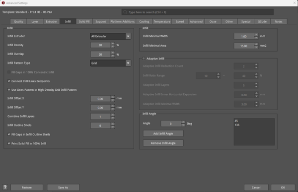
Figure 17: The Infill tab.
