
(1) Top and Down Solid Part
Base Solid Fill Layers: The number of solid layers for the first few layers of the solid part touching the platform or raft.
Base Solid Fill Layers does not include the First Layer, which is the layer in contact with the build plate or the Raft. For example, if Base Solid Fill Layers is 5, the bottommost layer is the First Layer. The 2nd layer is the Bottom Surface Solid Fill Layer. The 3rd to the 5th layers from bottom to up are the Base Solid Fill Layers, as shown Figure 1.
Solid Fill Layers: The number of solid layers for the solid part of the model.
For example, set the Base Solid Fill Layers to 5, and Solid Fill Layers to 4, you will see the model as shown in Figure 1.

Figure 1: Base Solid Fill Layers and Solid Fill Layers.
Base Solid Fill Pattern Type: The infill pattern for the first few layers of the solid part touching the platform or raft.
Solid Fill Pattern Type: The infill pattern for the solid part of the model.
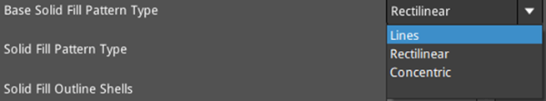
Figure 2: Select a Solid Fill Pattern Type depending on the model type.
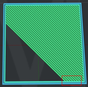
Figure 3: The “Solid Fill Pattern Type" is set to "Lines".
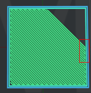
Figure 4: The “Solid Fill Pattern Type" is set to "Rectilinear".
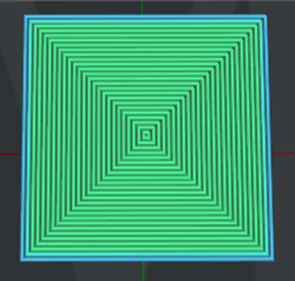
Figure 5: The “Solid Fill Pattern Type" is set to "Concentric".
Solid Fill Outline Shells: The number of outline shells in the solid fill layer to avoid solid fill layer collapse.
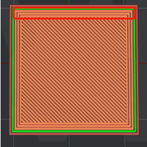
Figure 6: The "Solid Fill Outline Shells" is set to 3.
Solid Fill Minimal Width: The minimal extrusion width for printing solid fill structures. With this function enabled, you can avoid some jagged solid lines, as shown in Figure 7.
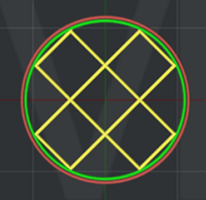
Figure 7: The "Solid Fill Minimal Width" is set to 0.8 mm.
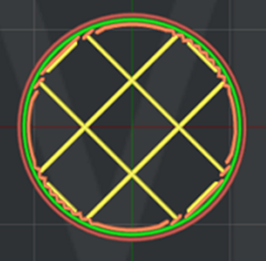
Figure 8: The "Solid Fill Minimal Width" is set to 0 mm.
Solid Fill Expansion: Expands the solid fill regions by the defined distance. This function will provide a better adhesion to the upper layer. Disable this function by setting the value to 0.
Expand Solid Fill to Fill Small Hole: With this function enabled, ideaMaker will automatically expand the solid fill regions to fill any holes with a width smaller than those with the defined value.
For example, if you set the Expand Solid Fill to Fill Small Hole to 0.2mm, the hole will be ignored if the hole’s width is greater than 0.2mm (refers to the left model in Figure 9).
If you set the Expand Solid Fill to Fill Small Hole to 3mm, the hole will be printed as solid fill if the hole’s width is smaller than 3mm (shown by the model on the right in Figure 9).
Note:
1 Setting the value to 0 will disable this function.
2 This function will not create unnecessary solid fills like in the Solid Fill Expansion function, but only the region of fill holes will be expanded.
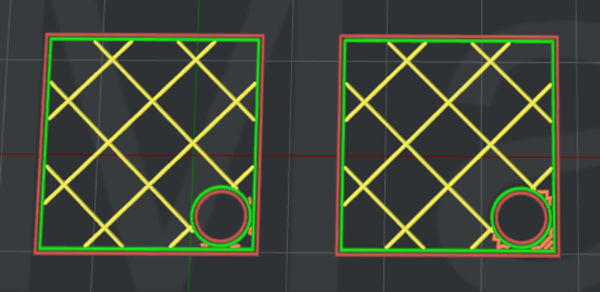
Figure 9: Slice with “Expand Solid Fill to Fill Small Hole” enabled.
Use concentric filling for narrow solid fill parts: With this function enabled, for narrow solid fill parts, the solid fill pattern type will be concentric.
(2) Monotonic Solid Fill
Monotonic fill creates printed objects with smoother, more-aligned top surfaces.
Base Monotonic Solid Fill: With this function enabled, the base solid fill will be printed in a specific monotonic order.
Monotonic Solid Fill: With this function enabled, the solid fill will be printed in a specific monotonic order.
Top Surface Monotonic Solid Fill: With this function enabled, the top and bottom surface solid fill will be printed in a specific monotonic order.
(3) Top and Down Solid Fill Angle
Top and Down Solid Fill Angle: Allows you to define the direction of each layer for the top and down solid fill structures. If you add 30º, 60º and 90º in the Angle box, the angle of the first layer of top and down solid fill structure will be 30º, the second layer will be 60º, and the third layer will be 90º. The fourth layer will be back to 30º, and the angle of the following layers will change accordingly based on this order.
Angle: The directional angle of top and down solid fill structure.
Add: Adds a value of the angle.
Remove: Removes the selected value of the angle.
(4) Top Surface Solid Fill
Top Surface Solid Fill Layers: The number of solid layers at the topmost of the model surfaces. Top Surface Solid Fill Layers are a part of Solid Fill Layers and this option will improve the surface quality.
You can set multiple Top Surface Solid Fill Layers so long as the number will not exceed the number of Solid Fill Layers. For example, if the number of Solid Fill Layers is 4 and the number of Top Surface Solid Fill Layers is 2, the topmost 2 layers are the top surface and the remaining 2 layers are the Solid Fill Layers, as shown in Figure 10.
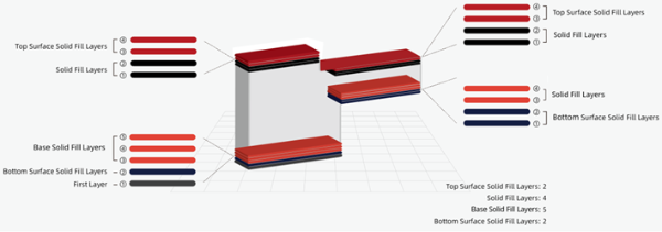
Figure 10: Top Surface Solid Fill Layers.
Top Surface Solid Fill Pattern Type:The infill pattern for the solid fills at the top of the model surface.
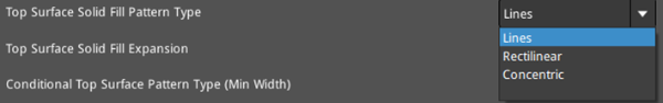
Figure 11: Select a "Top Surface Solid Fill Pattern Type" for your model.
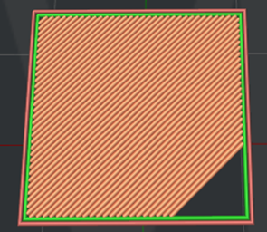
Figure 12: The "Top Surface Solid Fill Pattern Type" is set to "Lines".
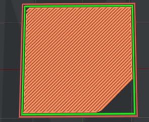
Figure 13: The "Top Surface Solid Fill Pattern Type" is set to “Rectilinear”.

Figure 14: The "Top Surface Solid Fill Pattern Type" is set to "Concentric".
Top Surface Solid Fill Expansion: With this function enabled, the solid fills at the top of the model surfaces are expanded in the X/Y direction to avoid different solid fill types in a single entire region.
Conditional Top Surface Pattern Type (Min Width): If the width of the top surface is less than this specified value, the top surface will be printed with the concentric fill pattern. Setting the value to 0 will disable this function.
Conditional Top Surface Pattern Type (Min Area): If the area of the top surface is less than this specified value, the top surface will be printed with the concentric fill pattern. Setting the value to 0 will disable this function.
(4) Bottom Surface Solid Fill
Bottom Surface Solid Fill Layers: The number of solid layers at the bottom of the model surfaces. Bottom Surface Solid Fill Layers are a part of Base Solid Fill Layers.
Modify the Bottom Surface Solid Fill Layers’ printing settings to improve overhang structures. You can set multiple Bottom Surface Solid Fill Layers so long as the number will not exceed the number of Base Solid Fill Layers.
Bottom Surface Solid Fill Pattern Type: The infill pattern for the solid fills at the bottom of the model surfaces.
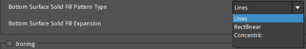
Figure 15: Select a "Bottom Surface Solid Fill Pattern Type" for your model.

Figure 16: The "Bottom Surface Solid Fill Pattern Type" is set to "Lines".
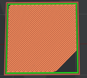
Figure 17: The "Bottom Surface Solid Fill Pattern Type" is set to "Rectilinear".
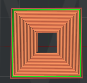
Figure 18: The "Bottom Surface Solid Fill Pattern Type" is set to "Concentric".
Bottom Surface Solid Fill Expansion: With this function enabled, the solid fills at the bottom of the model surfaces are expanded in the X/Y direction to avoid different solid fill types in a single entire region.
Note: It will expand the bridging regions if the bottom of the model surface is detected as a bridging structure.
(5) Ironing: With this function enabled, ideaMaker will print an Ironing layer with a small amount of flowrate at low speed after completing the top layer to provide a smooth and fine surface.
Ironing Flowrate: The flow rate for printing the ironing structure.
Ironing Speed: The printing speed for the ironing structure.
Ironing Monotonic: With this function enabled, the top layer will be ironed in a specific monotonic order.
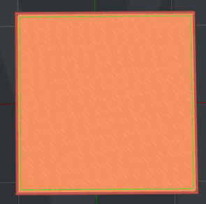
Figure 19: "Ironing" is Enabled.
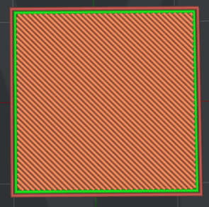
Figure 20: "Ironing" is Disabled.
Ironing Angle: The angle between the ironing lines and solid fill lines.
Ironing Line Distance: The distance between the ironing lines.
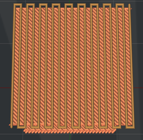
Figure 21: Slicing result when setting the Ironing Angle to 45 degrees and Ironing Line Distance to 1mm (The ironing line is brown and the solid fill line is orange).
Ironing Inset: The distance between the ironing lines and the edge of the model. The default value is 50% of the extrusion width.
Ironing Pattern: The pattern for the ironing layer of the model. There are two choices here: Rectilinear and Concentric.
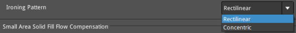
Figure 22: Select an Ironing Pattern for the ironing layer of the model.
Small Area Solid Fill Flow Compensation: With this function enabled, click the Edit button to open the Small Area Solid Fill Flow Compensation Model panel, and you can set the extrusion length and flow compensation factor for the solid fill. You can use the values in the list to determine the flow compensation factor for a given solid fill extrusion length, and then determine the actual flow value for this extrusion length based on the flow compensation factor. At the same time, use a chart to display the function curve of length and factor, which will change in real time with the corresponding settings.
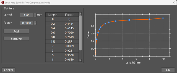
Figure 23: Small Area Solid Fill Flow Compensation Model panel.
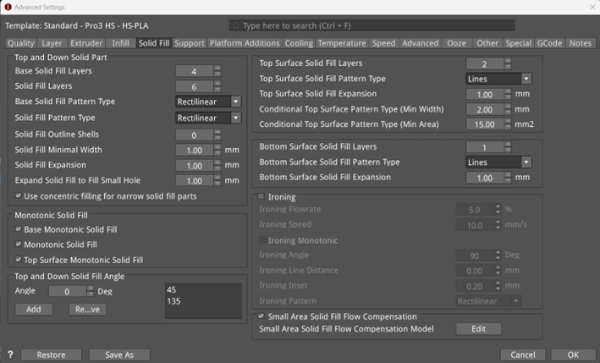
Figure 24: The Solid Fill Tab.
