
Generate Support: Adds support structure for the overhanging parts of the models.
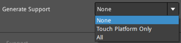
Figure 1: Generate support structure for overhang parts.
Ø None: Refers to no support structure for the model.
Ø Touch Platform Only: Only adds support structure which can touch the build plate. Support structures between two surfaces of the model will not be generated.
Ø All: Adds support structure for all the overhanging parts of the model.
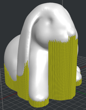
Figure 2: Select “Touch Platform Only” to generate supports.
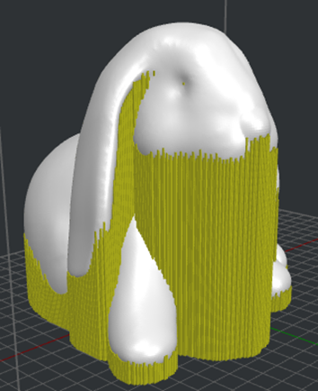
Figure 3: Select “All” to generate supports.
(1)Support
Support Extruder: Select the extruder that prints supports. If you have set the number of extruders to 1, it will only display Primary Extruder; If you have set the number of extruders to 2, it will display two options: Left Extruder and Right Extruder.
Support Type: The structure of the supports to be printed.
Ø Normal: The shape of the support is a normal shape, as shown in Figure 4.
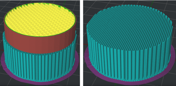
Figure 4: The Normal supports.
Ø Pillar: The shape of the support is a pillar shape, as shown in Figure 5.
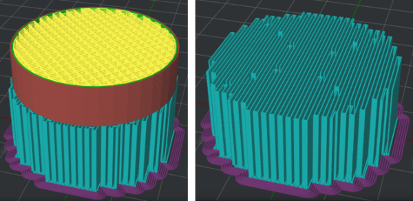
Figure 5: The Pillar supports.
Ø Tree: The shape of the support is a tree shape, as shown in Figure 6.
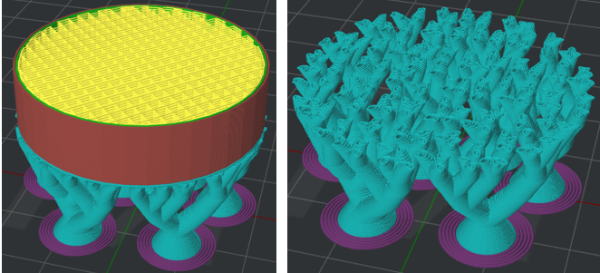
Figure 6: The Tree supports.
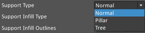
Figure 7: Select a support structure for your model.
Support Infill Type: The infill pattern for the support structure.
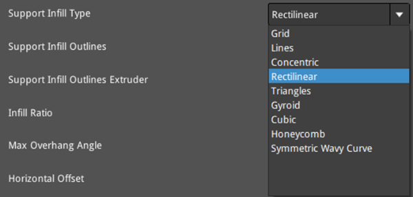
Figure 8: Select a support infill pattern for your model.
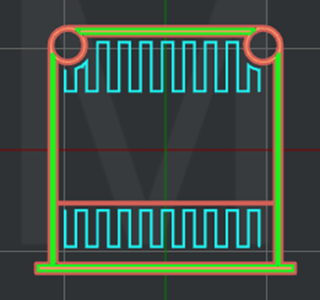
Figure 9: The "Support Infill Type" is set to "Lines".
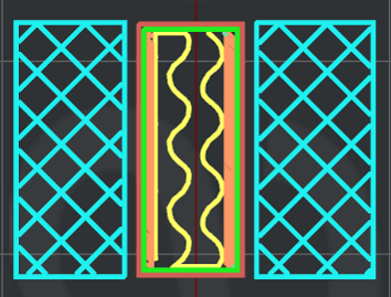
Figure 10: The "Support Infill Type" is set to "Grid".
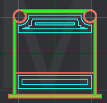
Figure 11: The "Support Infill Type" is set to "Concentric".
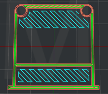
Figure 12: The "Support Infill Type" is set to "Rectilinear".
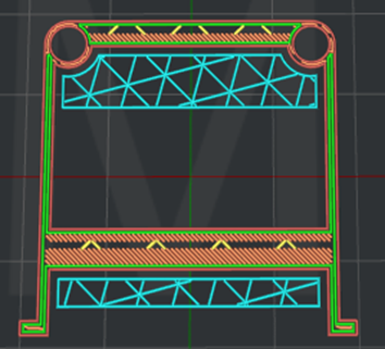
Figure 13: The "Support Infill Type" is set to "Triangles".
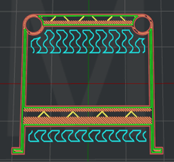
Figure 14: The "Support Infill Type" is set to "Gyroid".

Figure 15: The "Support Infill Type" is set to "Cubic".
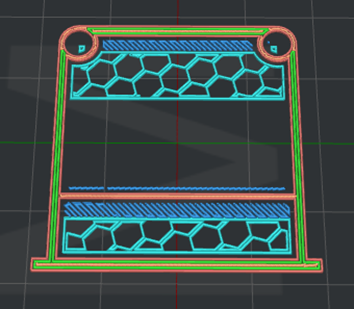
Figure 16: The "Support Infill Type" is set to "Honeycomb".
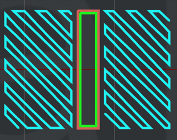
Figure 17: The "Support Infill Type" is set to "Symmetric Wavy Curve".
Support Infill Outlines: With this function enabled, ideaMaker will print some shells around the support, as shown in Figure 14.
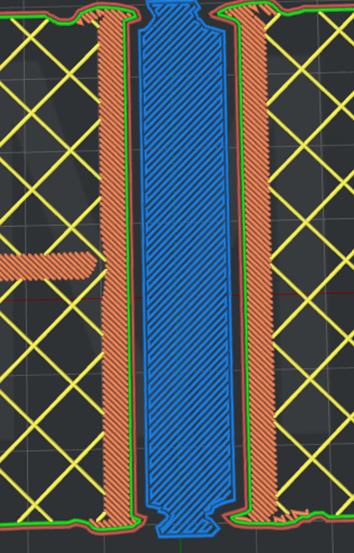
Figure 18: Enable “Support Infill Outlines”.
Support Infill Outlines Extruder: Select the extruder to print support infill outlines. If you have set the number of extruders to 1, it will only display Primary Extruder; If you have set the number of extruders to 2, it will display three options: All Extruder, Left Extruder and Right Extruder.
Infill Ratio: The density of support structure. When Adaptive Support is enabled, this function will be disabled.
Max Overhang Angle: Defines which parts of the model will have support added. When the real overhang angle on the model is greater than this defined value, support structure will be generated. Overhang Angle refers to the angle between the overhang surface and Z-axis.
Horizontal Offset: The distance between the support structure and the model parts in the X/Y direction.
Vertical Offset Top Layers: The number of layers between the top of the support structure and the model parts in a vertical direction.
Vertical Offset Down Layers: The number of layers between the bottom of the support structure and the model parts in a vertical direction.
Support Flowrate: The flow rate for printing the support structure.
Horizontal Expansion: With this function enabled, the support would be larger in the Horizontal direction and thus, can be removed more easily.
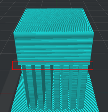
Figure 19: The "Horizontal Expansion" is set to 0.
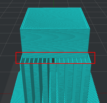
Figure 20: The "Horizontal Expansion" is set to 2.
Note: With the Horizontal Expansion function enabled, the angled support will be generated as shown in Figure 18.
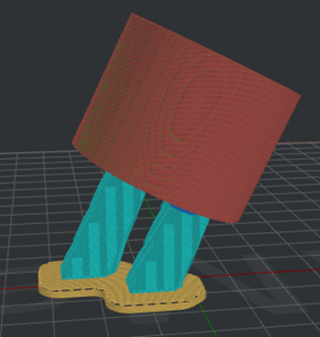
Figure 21: The angled support will be generated.
Solid Base Layers: The number of solid layers to increase adhesion of the support structure to layers below, as shown in Figure 19. Note: Support solid base layers will be generated at the supports touching the platform or Raft only.
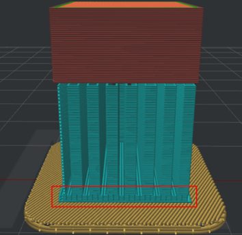
Figure 22: The "Solid Base Layers" is set to 5.
(2)Interlaced Support Infill Angle
Interlaced Support Infill Angle: You can define the direction of each layer of the infill structure which can decrease the potential of hangs in corners due to all support at the same direction. If you add 30º, 60º and 90º to the Angel box, the angle of the first layer of support will be 30º, the second layer will be 60º, and the third layer will be 90º. The fourth layer will be back to 30º, and the angle of the following layers will change accordingly in this order.
Angle: The directional angle of infill structure.
Add Infill Angle: Adds a value of the infill angle.
Remove Infill Angle: Removes the selected value of the infill angle.

Figure 23: The "Interlaced Support Infill Angle" is set to 30 degrees.
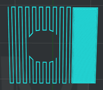
Figure 24: The "Interlaced Support Infill Angle" is set to 0.
(3)Other
Pillar Size: The size of each support pillar. This value is also used to determine where the pillar supports should be placed.
Add Sparse Connection: With this function enabled, ideaMaker will disable retraction between supports, which will ooze some filaments to connect and strengthen the supports.
Generate Support under Small Floated Features: With this function enabled, ideaMaker will automatically add support structures to hold the small floated features.
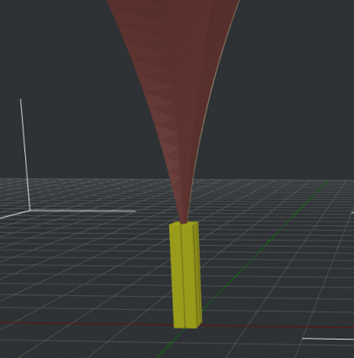
Figure 25: The "Generate Support under Small Floated Features" is Enabled.
Support Expansion under Small Floated Features: With this function enabled, the support structures for small floated features will be enlarged in the Horizontal direction to increase stability.
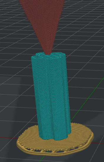
Figure 26: The "Support Expansion under Small Floated Features" is Enabled.
Recreate Support after Modifier Boolean Operation: With this function enabled, ideaMaker will automatically create new support structures for the result meshes after mesh boolean operations using the modifiers. With this function enabled, the existing manual support pillars will be ignored.
For example, set the Modifier’s type to Keep the overlap regions only (experimental), as shown in Figure 27.

Figure 27: Keep the overlap regions only (experimental).
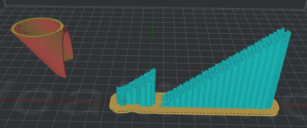
Figure 28: The “Recreate Support after Modifier Boolean Operation” is disabled. It only prints the existing manual supports that are generated before slicing, and the support will not be readjusted according to the final model structure.
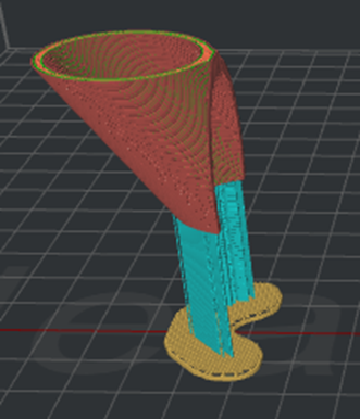
Figure 29: The “Recreate Support after Modifier Boolean Operation” is enabled. The support structures are regenerated according to the final model structure and the existing manual supports generated before slicing are ignored.
User Lines Pattern in High Density Grid Support Infill Pattern: With this function enabled, ideaMaker will change the support infill pattern to Lines automatically when the Grid support infill pattern is used, and the infill density is not less than 25%.
(4)Tree Support
Tree Support Branch Diameter: Controls the minimum and maximum diameter range of the branches.
Tree Support Branch Angle: This option specifies the maximum allowed overhang angle of branches when they are generated. The larger the angle is, the more horizontally oriented the generated branches tend to grow.
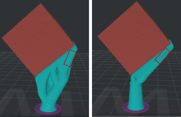
Figure 30: Comparison between tree support branch angles of 30 degrees (left) and 60 degrees (right).
Tree Support Branch Density: Controls the density of the tree support branches. Higher branch density results in more branches, which are harder to remove.
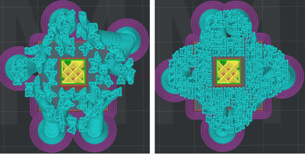
Figure 31: Comparison between tree support branch density of 30% (left) and 60% (right).
Branch Diameter Double Outlines: If the area of a tree branch exceeds the area of a circle with the specified diameter, the branch will be printed with double outlines to enhance stability. Setting the value to 0 will disable this function.
Note: If the model has already been manually added Pillar supports, additional-added Tree supports will not affect the original Pillar supports.
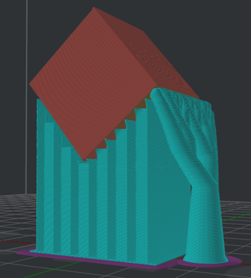
Figure 32: The model will Pillar supports as well as Tree supports.
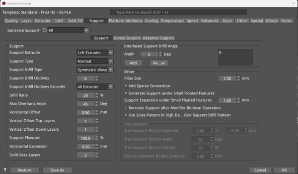
Figure 33: The Support Tab.
(5)Dense Support
Dense Support Layers: The number of layers for dense support structure. It will only exist in the layers approaching the model surface, which can make the support connecting points smoother after removing the supports.
Dense Support Bottom Layers: With this function enabled, you can define the number of dense support bottom layers. If it’s disabled, the number will be the same as the number of Dense Support Layers.
Dense Support Infill Ratio: The infill density of the Dense Support Layers.
Dense Support Infill Type: The infill pattern for the Dense Support Layers.
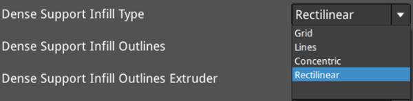
Figure 34: Select a dense support infill pattern for your model.

Figure 35: The "Dense Support Infill Type" is Set to "Lines".
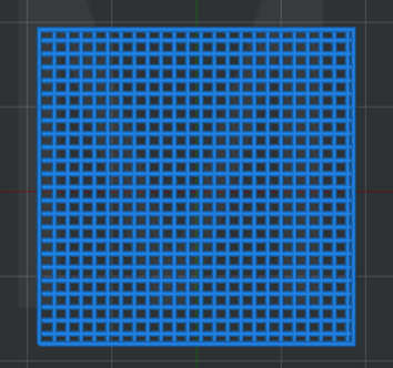
Figure 36: The "Dense Support Infill Type" is Set to "Grid".
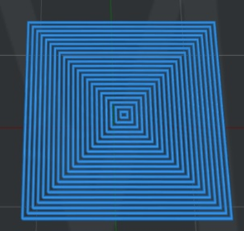
Figure 37: The "Dense Support Infill Type" is Set to "Concentric".
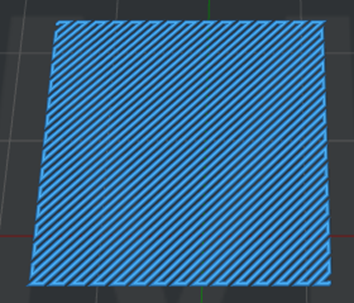
Figure 38: The "Dense Support Infill Type" is Set to "Rectilinear".
Dense Support Infill Outlines: With this function enabled, ideaMaker will print some shells around the dense support layers.
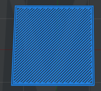
Figure 39: The "Dense Support Infill Outlines" is set to 2.
Dense Support Infill Outlines Extruder: Select the extruder to print dense support infill outlines. If you have set the number of extruders to 1, it will only display Primary Extruder; If you have set the number of extruders to 2, it will display three options: All Extruder, Left Extruder and Right Extruder.
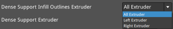
Figure 40: Select an extruder for dense support infill outlines.
Dense Support Extruder: Select the extruder to print dense supports. If you have set the number of extruders to 1, it will only display Primary Extruder; If you have set the number of extruders to 2, it will display three options: All Extruder, Left Extruder and Right Extruder.
Dense Support Inner Horizontal Expansion: With this function enabled, the dense support will be expanded in the X/Y direction to avoid narrow dense support regions, and it can be removed more easily. This function only works for the inner dense support structure located in the middle of supports.
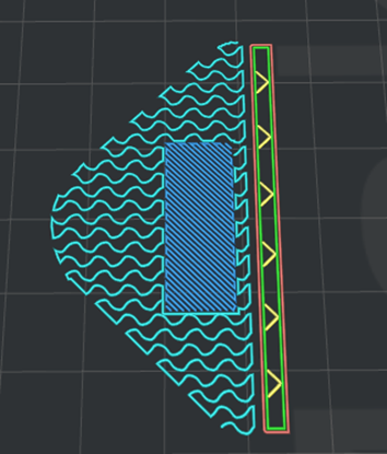
Figure 41: The "Dense Support Inner Horizontal Expansion" is set to 2mm.
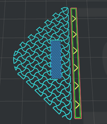
Figure 42: The "Dense Support Inner Horizontal Expansion" is set to 0mm.
Use Lines Pattern in High Density Grid Dense Support Infill Pattern: With this function enabled, ideaMaker will change the dense support infill pattern to Lines automatically when the Grid dense support infill pattern is used and the infill density is not less than 25%.
Dense Support Flowrate: The flow rate for printing the dense support structure.
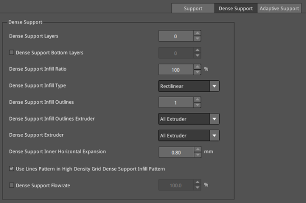
Figure 43: The Dense Support tab.
(6)Adaptive Support
Adaptive Support: Generates denser supports near the model surface, providing a more stable support structure.
Adaptive Support Reduction Count: The number of reductions for reducing the infill ratio of support structure. Each reduction will half the infill ratio of the support structure.
Infill Ratio Range: The minimum and maximum range of the support structure infill ratio. Note: when the dense support is enabled, the maximum infill ratio will be set to the Dense Support Infill Ratio.
Adaptive Support Layers: The number of layers before reducing the infill ratio of support structures.
Adaptive Support Inner Horizontal Expansion: With this function enabled, the adaptive support structure will be expanded in the X/Y direction to avoid narrow support regions and make the removal of supports easier.
Adaptive Support Minimal Width: The minimal width of the adaptive support structures. If the width of the adaptive support is less than the value you set, it will be merged into other support regions with different support infills.
Notes:
1. Support Infill Ratio and Dense Support Infill Ratio settings will be ignored if Adaptive Support is enabled.
2. Support Infill Type, Support Infill Ratio, Dense Support Infill Type and Dense Support Infill Ratio settings in Modifier settings will be ignored if Adaptive Support is enabled.
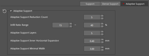
Figure 44: The Adaptive Support tab.
