
(1) Left Extruder
Clearance Settings for Sequential Printing:
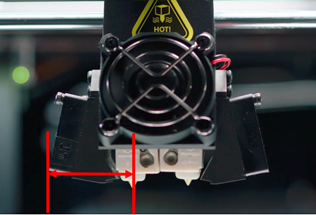
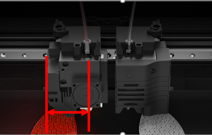
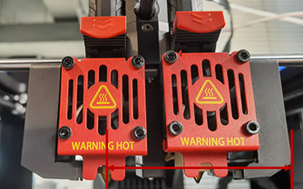
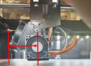
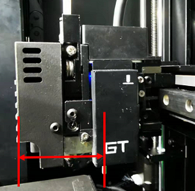
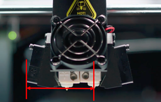
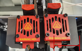
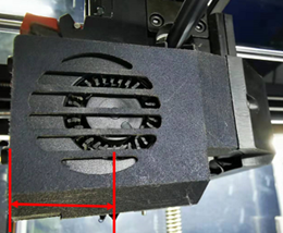
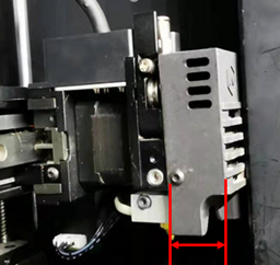
Offset from printhead left to the nozzle: The distance between the left nozzle and the left cooling fan or the fan cover, as shown in Figure 1. (Note: Figure 1 is only for illustration, and the actual extruder’s appearance may differ to the actual product.)
Raise3D Pro2 Series Printer
Raise3D Pro3 Series Printer
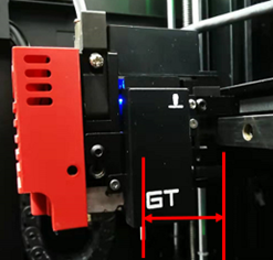
Raise3D Pro3 HS Series Printer
Raise3D E2CF Printer
Raise3D E2 Printer
Raise3D RMF500 Printer
Figure 1: Offset from printhead left to the nozzle.
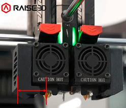
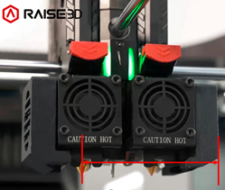
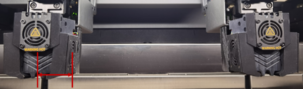
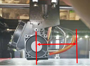
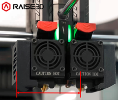
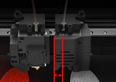
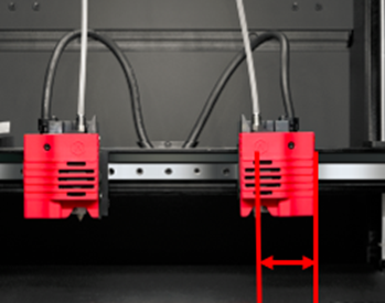
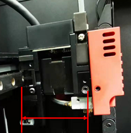
Offset from printhead right to the nozzle: The distance between the left nozzle and the right cooling fan for Raise3D Pro2 Series, Pro2 Hyper Speed Series, Pro3 Series, Pro3 Hyper Speed Series, Pro3 HS Series and RMF500 printers. It refers to the distance between the left nozzle and the left printhead's Z Probe for Raise3D E2 and E2CF printers, as shown in Figure 2. (Note: Figure 2 is only for illustration, and the actual extruder’s appearance may differ to the actual product.)
Raise3D Pro2 Series Printer
Raise3D Pro3 Series Printer
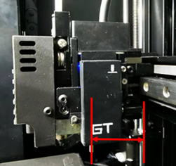
Raise3D Pro3 HS Series Printer
Raise3D RMF500 Printer
Raise3D E2CF Printer
Raise3D E2 Printer
Figure 2: Offset from the printhead right to the Nozzle.
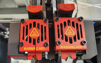
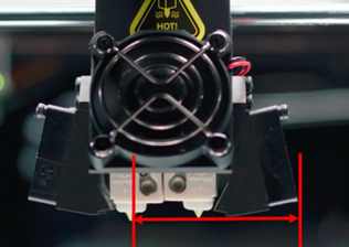
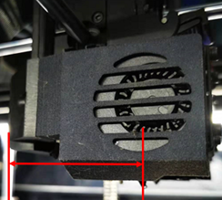
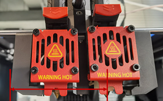
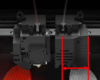
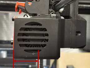
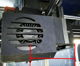
Offset from printhead front to the nozzle: The distance between the left nozzle and the front cooling fan or the fan cover for the Raise3D Pro2 Series, Pro2 Hyper Speed Series, Pro3 Series, Pro3 Hyper Speed Series, Pro3 HS Series and RMF500 printers. It refers to the distance between the left printer head’s Z probe and the left printhead cover's front side for Raise3D E2 and E2CF printers, as shown in Figure 3. (Note: Figure 3 is only for illustration, and the actual extruder’s appearance may differ to the actual product.)
Raise3D Pro2 Series Printer
Raise3D Pro3 Series Printer
Raise3D Pro3 HS Series Printer

Raise3D RMF500 Printer
Raise3D E2CF Printer
Raise3D E2 Printer
Figure 3: Offset from printhead front to the nozzle.
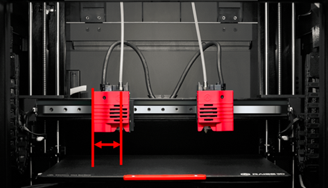
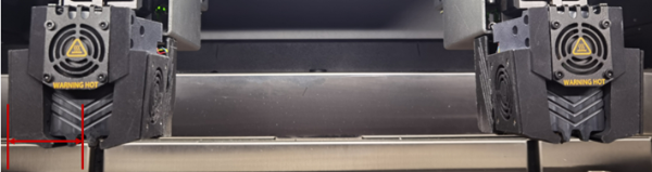
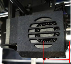
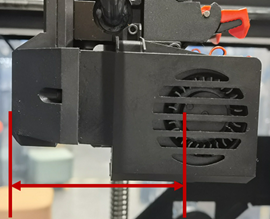
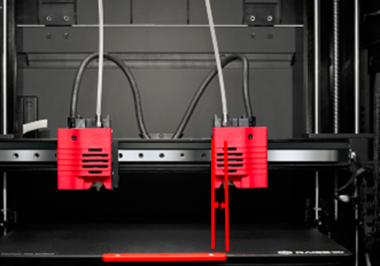
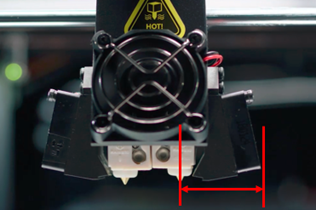
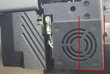
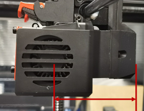
Offset from printhead back to the nozzle: The distance between the left nozzle and the printhead’s backside for the Raise3D Pro2 Series, Pro2 Hyper Speed Series, Pro3 Series, Pro3 Hyper Speed Series and Pro3 HS Series printers. (Note: The printhead’s backside should include cables.) It also refers to the distance between the X-axis guide rail’s front side and the nozzle for the Raise3D E2 and E2CF printers. For the Raise3D RMF500 printers, it refers to the distance between the left nozzle and the backside of the PCB cover, as shown in Figure 4. (Note: Figure 4 is only for illustration, and the actual extruder’s appearance may differ to the actual product.)
Raise3D Pro2 Series Printer
Raise3D Pro3 Series Printer
Raise3D Pro3 HS Series Printer
Raise3D E2CF Printer
Raise3D E2 Printer
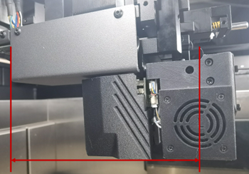
Raise3D RMF500 Printer
Figure 4: Offset from printhead back to the nozzle.
Temperature Limit:
Left Extruder Maximum Temperature Limit: The maximum temperature for the left extruder during printing.
Customize Toolhead Identifier: With this function enabled, users can edit the nozzle’s identifier manually.
Notes:
1. It works for third-party printer only.
2. Please confirm your printer’s nozzle format before editing the toolhead identifier.
Customize Extruder Printable Region: Different printers have different default printable area ranges.
X/Y: The starting point position for printing on the X/Y axis.
X/Y Size: The maximum printable size on the X/Y axis, measured in millimeters.
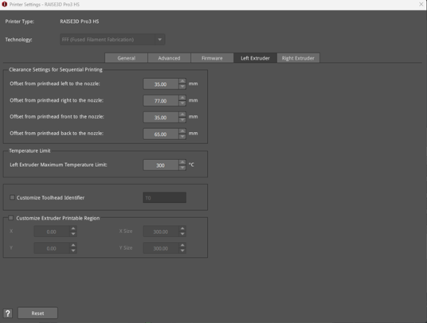
Figure 5: The Left Extruder tab in the Printer Settings panel.
(2) Right Extruder
Clearance Settings for Sequential Printing:
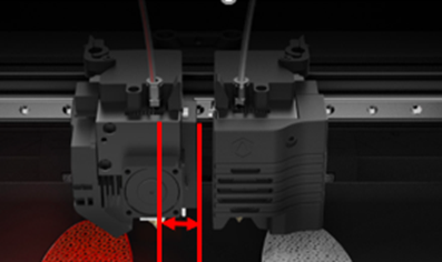
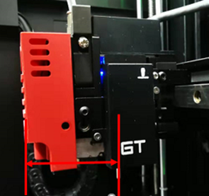
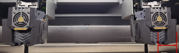
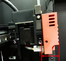
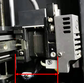
Offset from printhead left to the nozzle: The distance between the right nozzle and the left cooling fan for the Raise3D Pro2 Series, Pro2 Hyper Speed Series, Pro3 Series, Pro3 Hyper Speed Series and Pro3 HS Series printers. It refers to the distance between the right printhead’s nozzle and the right printhead fan cover's left side for Raise3D E2, E2CF and RMF500 printers, as shown in Figure 6. (Note: Figure 6 is only for illustration, and the actual extruder’s appearance may differ to the actual product.)
Raise3D Pro2 Series Printer
Raise3D Pro3 Series Printer
Raise3D Pro3 HS Series Printer
Raise3D E2CF Printer
Raise3D E2 Printer
Raise3D RMF500 Printer
Figure 6: Offset from printhead left to the nozzle.
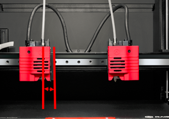
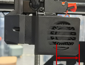
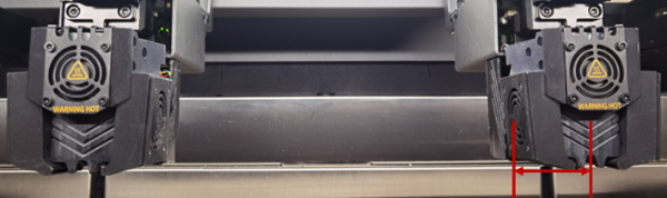
Offset from printhead right to the nozzle: The distance between the right nozzle and right cooling fan cover, as shown in Figure 7. (Note: Figure 7 is only for illustration, and the actual extruder’s appearance may differ to the actual product.)
Raise3D Pro2 Series Printer
Raise3D Pro3 Series Printer
Raise3D Pro3 HS Series Printer
Raise3D E2CF Printer
Raise3D E2 Printer
Raise3D RMF500 Printer
Figure 7: Offset from printhead right to the nozzle.
Offset from printhead front to the nozzle: The distance between the right nozzle and the front cooling fan for the Raise3D Pro2 Series, Pro2 Hyper Speed Series, Pro3 Series, Pro3 Hyper Speed Series, Pro3 HS Series and RMF500 printers. It refers to the distance between the right printhead’s nozzle and the right printhead cover's front side for Raise3D E2 and E2CF printers, as shown in Figure 8. (Note: Figure 8 is only for illustration, and the actual extruder’s appearance may differ to the actual product.)

Raise3D Pro2 Series Printer
Raise3D Pro3 Series Printer
Raise3D Pro3 HS Series Printer
Raise3D RMF500 Printer
Raise3D E2CF Printer
Raise3D E2 Printer
Figure 8: Offset from printhead front to the nozzle.
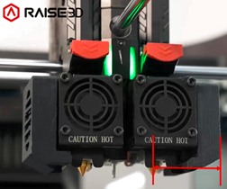
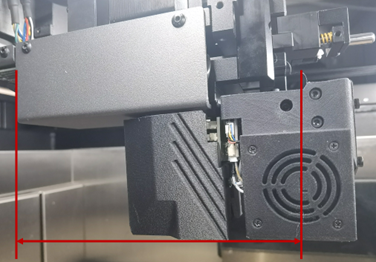
Offset from printhead back to the nozzle: The distance between the right nozzle and the printhead’s backside for Raise3D Pro2 Series, Pro2 Hyper Speed Series, Pro3 Series, Pro3 Hyper Speed Series and Pro3 HS Series printers. (Note: The printhead’s backside should include cables.) It also refers to the distance between the X-axis guide rail front side and the nozzle for Raise3D E2 and E2CF printers. For the Raise3D RMF500 printers, it refers to the distance between the right nozzle and the backside of the PCB cover, as shown in Figure 9. (Note: Figure 9 is only for illustration, and the actual extruder’s appearance may differ to the actual product.)

Raise3D Pro2 Series Printer
Raise3D Pro3 Series Printer
Raise3D Pro3 HS Series Printer
Raise3D E2CF Printer
Raise3D E2 Printer
Raise3D RMF500 Printer
Figure 9: Offset from printhead back to the nozzle.
Temperature Limit:
Right Extruder Maximum Temperature Limit: The maximum temperature for the right extruder during printing.
Customize Toolhead Identifier: With this function enabled, users can edit the nozzle’s identifier manually.
Notes:
1. It works for third-party printer only.
2. Please confirm your printer’s nozzle format before editing the toolhead identifier.
Customize Extruder Printable Region: Different printers have different default printable area ranges.
X/Y: The starting point position for printing on the X/Y axis.
X/Y Size: The maximum printable size on the X/Y axis, measured in millimeters.
Extruder Offset:
Extruder Offset X: Refers to the offset between two nozzles in the direction of X-axis. We set the left extruder as the default nozzle. When we calculate the correct extruder’s position, we should subtract 25mm offset (which you set for X offset) in the X-axis direction.
Extruder Offset Y: Refers to the offset between two nozzles in the direction of Y-axis. We set the left extruder as the default nozzle. When we calculate the correct extruder’s position, we should subtract 0mm offset (which you set for Y offset) in the direction of Y-axis.
Virtual Extruder Offset X: Refers to the right extruder’s virtual offset on the X-axis.
Virtual Extruder Offset Y: Refers to the right extruder’s virtual offset on the Y-axis.
Note: The value is used to check whether models are placed outside the extruder’s printing range if both Extruder Offset X and Y are set to 0.
For example, if you set Virtual Extruder Offset X to 0mm and choose the right extruder for printing, you will see the printing range is same as the left extruder, as shown in Figure 10. If you set Virtual Extruder Offset X to 25mm and choose the right extruder for printing, you will see the printing range as shown in Figure 11.
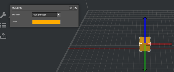
Figure 10: Set Virtual Extruder Offset X to 0mm.
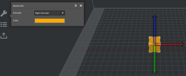
Figure 11: Set Virtual Extruder Offset X to 25mm.
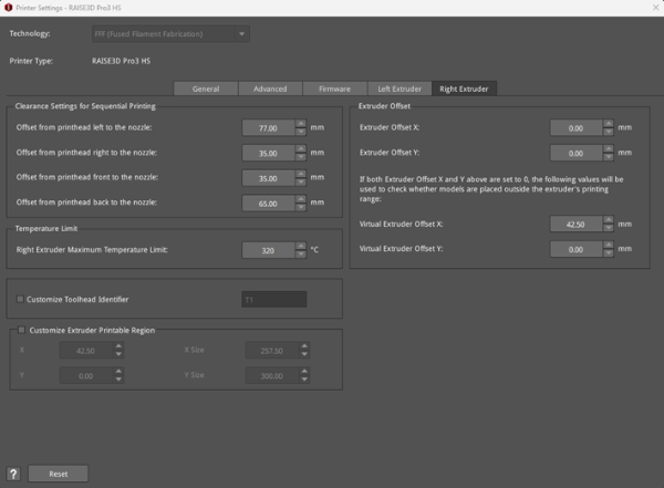
Figure 12: The Right Extruder tab in the Printer Settings panel.
