
[ Manual Pro 2 Series – How to Calibrate the Nozzle Offsets – V1.2 ]
Correctly calibrated nozzles on a 3D printer is essential for a quality printed result. However, Raise3D breaks down the steps to calibrating the nozzles for our Pro 2 and Pro 2 Plus 3D printers here using Model 1 and Model 2 as a tester. There are six total sections: preparation, print calibration using model 1, measuring the offset, adjusting the offset, print calibration using model 2, and compare model 1 and model 2 printing results.
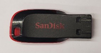
①USB Drive
1.Ensure Nozzle heights are calibrated properly before calibrating offsets.
Note: See our tutorial Manual Pro2 Series - How to Calibrate the Nozzle Height - V1.0 on how to calibrate the nozzle height.
2.Ensure Bed flatness is calibrated properly before calibrating offsets.
Note: See our tutorial Manual Pro2 Series - How to Calibrate the Bed Leveling - V1.0 on how to level the bed.
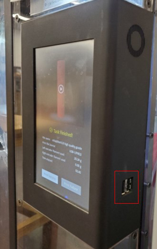
1.First locate the USB storage drive that was included within the accessory box of your Pro2 Series packaging. Connect this drive to an available USB port on the right side of the touchscreen.
2.Ensure PLA is loaded into both extruders.
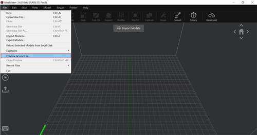
3.Open ideaMaker, and click “Preview GCode File” in the "File" submenu, locate the pre-sliced files included in the Pro 2 Series flash drive. Select “Dual Head Calibration 1. GCode” model, and start to print.
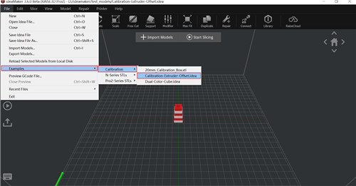
4.If you do not have your flash drive with this file, or would like to use a filament other than PLA, you can find the model in ideaMaker under File>Examples>Calibration>Calibration-Extruder-Offset.idea.
Note: Raise3D recommends printing with a wipe wall or wipe tower for the best results.
5.View the printed model from the top surface and align this to the visual graphic seen on screen. The direction can be identified with the large notch along the Y-direction, and the small notch in the X-direction.
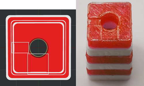
1.The model printed under ideal condition (when the XY offset of both the left and right nozzles is 0) should be like:
2.It can be seen that the surrounding spacing of each layer is equal. Below is a top view.
Note: Since the relative positions of the left and right nozzles are fixed, the XY axis offset of the nozzle is calibrated using the left nozzle as the reference to adjust the offset value of the right nozzle, so the X-axis position of the left nozzle is 0mm and cause the distance between the left and right nozzles is 25mm, so the X-axis position of the right nozzle is 25mm.
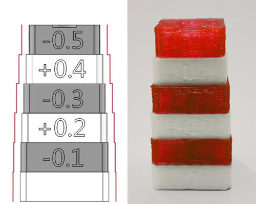
3.If the right nozzle offsets on either X-axis direction or Y-axis direction, then according to the example given below.
Note: The direction of the X and Y axis can be distinguished according to the size of the top notch, the smaller notch is X axis, the larger notch is Y axis.
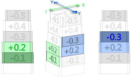
4.It can be seen from the pics that the printed model is almost straight on the left side of the second and third layers in the X-axis and almost straight on the right side of the third and fourth layers in the Y-axis.
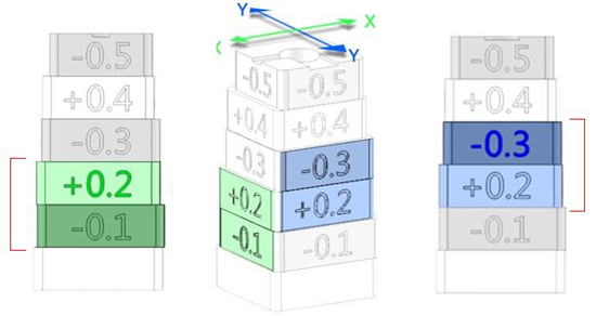
5.The value on the upper layer of the two aligned layers, is the offset value, and according to the example above, right nozzle’s X-axis offset value is +0.2mm, and the Y-axis value is -0.3mm.
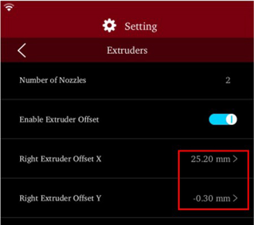
1.Input the offset value at “Setting > Machine > More Settings > Hardware > Extruders”.
“Right Extruder Offset X” is 25.2mm, and “Right Extruder Offset Y” is -0.3mm.
Note: “Right Extruder Offset X” is 25mm+0.2mm=25.2mm, and “Right Extruder Offset Y” is 0mm-0.3mm=-0.3mm.
1.Connect the same USB drive used above to an available USB port on the right side of the touchscreen.
2.Ensure PLA is loaded into both sides.
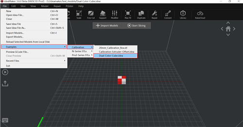
3.Open ideaMaker, and click “Preview GCode File” in the "File“submenu, locate the pre-sliced files included in the Pro 2 Series flash drive. Select “Dual Head Calibration 2.gcode” model, and start to print.

4.If you do not have your flash drive with this file, or would like to use a filament other than PLA, you can find the model in ideaMaker under File>Examples>Calibration>Dual-Color-Cube.idea.
Note: Raise3D recommends printing with a wipe wall or wipe tower for the best results.
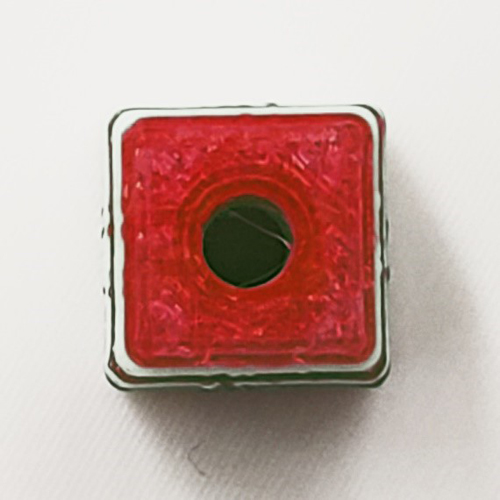
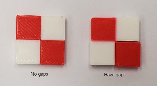
1.Check for obvious gaps between the colored blocks (refer to the diagram below)
[ Manual Pro 2 Series – How to Calibrate the Nozzle Offsets – V1.2 ]
- END -
