
The Pro3 Series is equipped with an independent modular extruder with a dual extrusion system. This allows the Pro3 Series to print using a variety of filaments, reduce clogging, and enables convenient disassembly and replacement of components. This tutorial will systematically show how to load two spools of filaments, how to set up dual printing in ideaMaker, and introduce the related basic and advanced settings of dual printing.
With the accessories kit that comes with the Pro3 Series printer, two spools of Raise3D Premium PLA filament are included. Please load these two spools of filament into the left and right hotend, respectively.
1. Open the right-side door of the printer and mount the filament spool holder to an appropriate installation point. Prepare a spool of Raise3D Premium PLA printing filament and install it onto the holder.
Note: If filament is mounted at points B and D, it is recommended to place the filament winding end in a clockwise direction. If filament is mounted at points A and C, it is recommended to place the filament winding end in a counterclockwise direction.

2. Continuously depress the ring of the quick connector, at the top of the printhead, and carefully pull out the filament guide tube.

3. Locate the loose end of the filament, and pass the filament end through the appropriate left/right sensor inlet and into the guide tube.
Note: This guide will use the left side as an example. The procedure for the left side is the same as the right side. Both the left and right sensor inlets are shown in the figure, below.

4. After feeding filament through the guide tube and into the top of the left printhead, select the “Utilities” tab at the bottom of the touchscreen, and set the left nozzle (L-Nozzle) temperature to an appropriate printing temperature for the filament you are using.
For example, the default loading temperature of Raise3D Premium PLA is 215°C. Here, the left nozzle temperature can be set to 215°C.
Note: Generally, the recommended loading and unloading temperature of any filament should be 5-10°C higher than the normal printing temperature.

5. Press “Load”, and the left nozzle will begin to heat. When the hotend reaches the target temperature, press the “Load” button to load the filament into the printhead.
Note: These instructions are based on the properties of Raise3D Premium PLA filament. This is the standard filament included with your printer and we recommend using Raise3D Premium PLA for the initial setup procedures and any subsequent testing purposes.
The extruder gear will start to rotate. Gently guide the filament downward into the printhead, by hand, to assist the filament engaging with the rotating extruder gear inside. When filament begins to extrude from the nozzle, press “OK” to complete the loading cycle. Insert the guide tube back into the quick connector.

Slice your model using our free slicing software, ideaMaker. It is helpful to ensure that the latest version of ideaMaker is installed on your computer. Please click the link below to check for the latest available version: https://www.raise3d.com/download/. The model used in this tutorial is a test model provided in the USB flash drive within the accessories kit box, which is suitable for dual printing. Mount the USB flash drive to your computer to access the model.
1. Open ideaMaker, click the "+" button to import the test model named "Giveaway Spinner". The model has two parts, the inner circle A and the outer ring B.

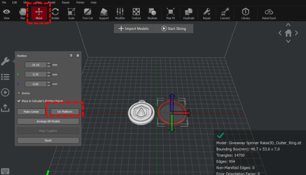
2. With the model(s) selected, click “Move > On Platform” to place the model(s) on the build plate. Laying the model flat on the build plate allows you to use less support (or eliminate the need) for the model, thus improving the printing efficiency.
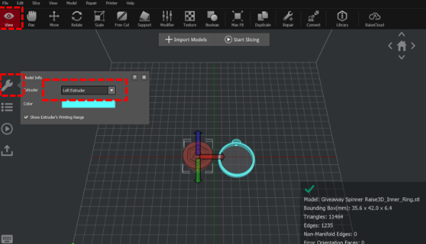
3. Select one of the two models, click “View > Model Info (wrench icon) > Extruder” on the left side, and select “Left Extruder” in the drop-down list. Each nozzle has a different printing range. You can tick the “Show Extruder’s Printing Range” to display the printable area of the nozzle. You can also assign different colors to each nozzle to distinguish them.
4. Select the other model, while still in View mode, click “Model Info > Extruder” on the left side, and select the right nozzle in the drop-down list.

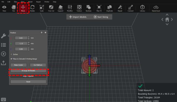
5. Press the “Ctrl” and “A” keys at the same time to select all models. Then click “Move > Align Together” to align the models. The “Align Together” function can align multiple models according to their original relative position (original relative position refers to the original position of the model in the modeling process).
6. Click “Start Slicing”, select the appropriate Printer model, the filament you used and the template. Click “Edit” or double-click the template to enter the advanced settings interface to view or adjust additional parameters.

7. You can select the type of Platform Addition in the “Edit Template” drop-down list.
There are three types of Platform Addition: Raft/Brim/Skirt.
Raft is a removable printed part that serves as a smooth platform to ensure first layer quality. A raft can enhance the adhesion between the model and the build plate and reduce the risk of model warping.
Note:
1. It is not recommended to print Raft when printing flexible filaments.
2. It is not recommended to print Raft with PVA filaments.
3. If the model size is larger than 150mm, it is recommended to use a Raft first.
Brim is an outward extension of the first layer of the model (like the brim of a hat) that allows for better adhesion to the printing surface.
Skirt is a single layer of extruded outlines, not connected to the model, that helps with priming before starting the actual print.

8. You can select the type of Support in the “Support” drop-down list.
There are three types of Support: None/Touch Platform Only/All.
None refers to no support structure will be added for the model.
Touch Platform Only refers to only adding support structures which can touch the build plate. Any supports added from one surface of the model to another surface of the model will not be created.
All refers to adding support structures to all the overhanging parts of the model.
Note: If model A is stacked on model B, ideaMaker will not be able to detect whether support structure will be created for model A. ideaMaker will open a window with the message, “The model is not on the build platform and has no support, do you want to assess support structures?” If the model does not need support, you can click “No” to not add support structures to the model.

9. In the “Edit Template” interface, click “Advanced” to view and modify additional parameters.

10. Under “Advanced Settings”, users can adjust the retraction amount of the filament in the “Extruder” tab.
Retract Material Amount refers to the amount of filament drawn backward to avoid stringing when the nozzle quickly moves from point A to point B.
Retraction Amount of Extruder-switch refers to the amount of filament retraction for an extruder change. 0 refers to no retraction at all.
Note: It is recommended to use the default parameters for Raise3D official filaments. For third-party filaments, appropriate adjustments are required.

11. A user can adjust the “Inactive Cooling Temperature” in the “Temperature” tab.
Inactive Cooling Temperature means that when this function is enabled, the inactive nozzle will lower to the set temperature during printing.
For example: When the right nozzle is idle while the left nozzle is printing, the temperature of the right nozzle is still hot enough to extrude filament. The resting filament in the hotend will melt to a liquid state and drip onto the model, resulting in dyeing of the model. To avoid this issue, the temperature of the idle nozzle can be reduced to a state where the filament will not melt and drip. Enabling this idle temperature function, however, will increase the printing time.

12. Users can adjust parameters such as “Wipe Wall” in the “Oozing” tab.
Enable Wipe Wall will add extra shell(s) around the model during dual-extruder printing. This wall(s) can help clean the oozing filament from the unused nozzle to reduce the oozing of the model on the model.
Wipe Wall Offset refers to the distance between Wipe Wall and the outer shell of the model. If the wall is positioned too closely, the Wipe Wall may stick onto the model. If the wall is set too far, the wiping results may be affected.
Wipe Wall Angle refers to the maximum angle for generating the Wipe Wall. If the maximum angle is set too low, the wall may have a difficult time following the shape of the model, especially around curved surfaces in the Z-axis.
Wipe Wall Loop Lines refers to the quantity of the shells used to construct the wipe wall.
Wipe Wall Type refers to the shape of Wipe Wall. There are the following 3 types of Wipe Wall. The difference between them is the distance between the Wipe Wall and the model.
Contoured is the Wipe Wall structure closest to the shape of the original model. In some cases, it will be too close to the model, which may be difficult to remove, especially the inner structures.
Water Fall will be generated along the origin shape, but if the lower structure is more narrow than the upper structure, a vertically dropping wall will be created.
Vertical type wipe wall will be created at the widest part of the model. It is ideal for simple structures like tubes or cubes.

13. Dual-extruder printing with Multiple Filament Types
Printing with multiple filament types may limit printing compatibility. The table below lists all of the officially-supported dual-extruder printer material combinations currently possible on the Pro3 series printers.

14. How to Print PVA Filament
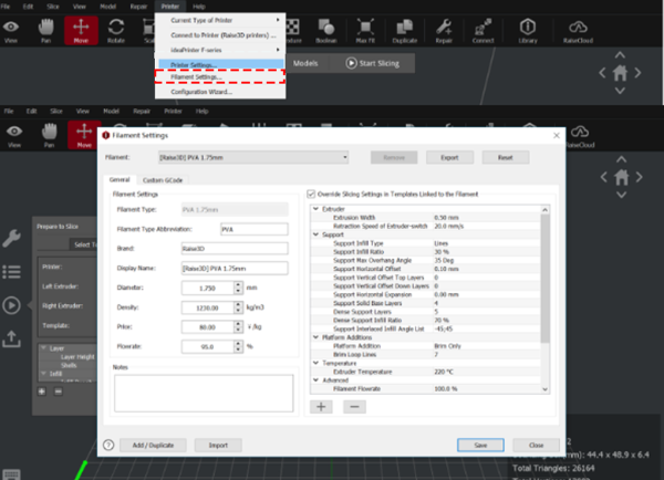
When a nozzle is assigned to print with PVA filament, ideaMaker will automatically edit some additional settings to get better printing performance with PVA filament. This will disable some settings under the “Advanced” menu and these settings will not be directly editable. If you want to edit these settings, you can navigate to “Printer > Filament Settings > PVA 1.75mm”; Or you can directly click the pencil icon on any tabs of “Advanced Settings” and ideaMaker will directly jump to the filament template, making it convenient for you to edit the parameters.
Method 1
Method 2

For how to print with PVA+ filament, please refer to How to set up PVA+ Filament for Printing.
15. After a parameter is edited, you can click “OK” on the “Advanced Settings” interface to save the changes, and click “Slice” on the “Select Template” interface to slice the model.

16. After the model is sliced, click “Export” in the pop-up window “Estimated Print Result” to save and import the .gcode and .data files into your USB flash drive.
Note: File names that do not conform to the Western Latin character set may not display properly.

1. Before starting dual printing, please calibrate the left and right nozzle heights and X/Y offset values of your Pro3 series printer to ensure that the printer can perform dual printing normally.
1) How to calibrate the Nozzle Height, please refer to How to Calibrate the Nozzle Height.
2) How to calibrate the X/Y offset value, please refer to How to Calibrate the Right Nozzle XY Offset.
1.Insert the USB device that contains your sliced model files (.gcode and .data) into an available USB port on the side of the touchscreen.

2. Select the “Print” tab on the touchscreen, and choose “USB Storage” to open the connected USB drive. Select your sliced model file to check the printing parameters and settings.
Select “Print” to start printing the model.

3. During the printing process, you can check the printing status from the “Home” tab interface on the touchscreen, including the remaining printing time and other parameters.
Note: The touchscreen will display an image of your model during printing. This image will only be shown when the file is sliced by ideaMaker and the .data file is exported to the USB flash drive.

